
How to build a passive crossover network
Passive crossover build guide
We’ve designed a crossover before, now it’s time to learn how to build a passive crossover. There are different techniques to building a passive crossover network. Some are basic, some are more advanced and more clean looking. However, I’m going for the middle ground. I mix soldering, crimping, gluing, zipping to make the filter look clean, but at the same time, easy to make.
I’m not going to show you, how the crossover is designed. If you are interested in that, you maybe want to take a look at :
- Passive crossovers basics
- Passive crossover designs with circuit diagrams
- Design a crossover without measuring equipment
- Design a crossover using SoundEasy
Now that we got that out of the way, here is the schematic for the crossover we are going to build :
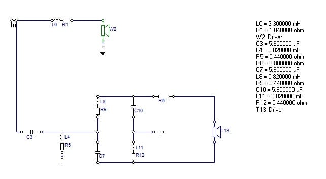
This is a 2nd order Linkwitz Riley filter. Actually, it’s an asymmetrical filter, with a first order slope for the woofer and a 2nd order slope for the tweeter. The tweeter also has a ladder delay network and an attenuation resistor.
How to build a passive crossover – first step
The first step I like to take is to make the cables for the speakers and binding posts.

I try to use thick cables, as thick as the crimp connector allows. Use appropriate crimp connectors for you binding posts (Amazon affiliate paid link). This should be a short cable. In fact all the cables should be as short as possible. I trimmed them after I took this picture. But the cables for the mid-bass should be a bit longer, and for those I used 6.3 mm spade crimp terminals. (middle row). Tweeter cables should also be a bit longer (for reaching purposes) and use 2.8 mm spade crimp terminals for these. Leave the other ends of the cables stripped for further processing.
The circuit board
First thing to do is to get a board to fit the components of the filter. Easiest thing to do is to use a thin piece of wood. However, even easier than this, is to get a piece of MDF that you used to make the enclosure. It’s a bit thick, but it will do. I like to glue 4 small legs to the board. This is because I use zip ties to fix some of the components. The board needs to be of sufficient size to accommodate the components. However, it also needs to be small enough to fit through the mid-bass hole. This board is 14 cm x 15 cm.

Remember, this is my view on how to build a passive crossover. I like to use zip ties on the inductors, and hide the ends of the zip-ties on the bottom of the board. Never use screws to fix the coils, it will alter the inductor value. Some have a plastic casing with a hole in the middle, and the first instinct is to drill a screw in the middle. In conclusion, don’t use metal fixing solutions for the inductors.
Using the 3 way crimp connector
I like to start with the biggest component, usually the inductor on the mid-bass side (L0). In our case the 3.3 mH one. I place it near a corner and work my way from there, so I don’t waste space. If you look at the circuit schematic, you will see that this inductor is connected to the positive input (amplifier +) and the tweeter section of the filter which begins with capacitor C3.
How to design loudspeakers - video courses


As a result, I like to use a 3 way crimp connector. This makes it easy to connect 3 components in one spot, using a crimping tool (Amazon affiliate paid link). Furthermore, I can screw it to the board using a small screw. I use a 3 mm drill bit to make holes for both the screws and for passing the zip ties.

Trim one end of the capacitor and crimp it to the connector. Crimp the inductor to the connector also. For the 3rd end of the connector, crimp the positive lead that goes to the positive speaker terminal (the mid-bass).

Placing the components on the board
Here is a pic after I placed some components, and let’s see how to build a passive crossover :
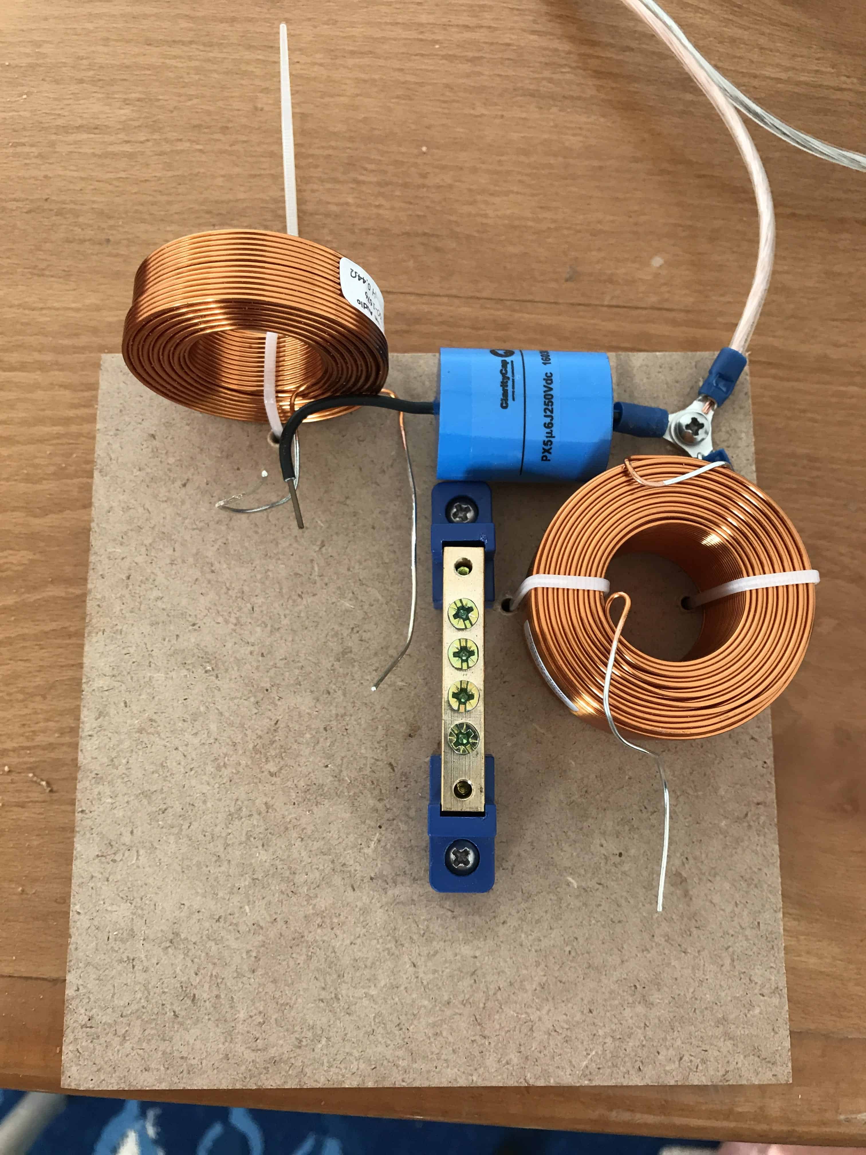
Comments on the above picture :
- Inductors are fastened to the board using zip ties. If the inductor is placed close to the edge, I drill only one hole and route the zip ties along the side of the board. Otherwise, drill two holes.
- Try to alternate inductor positioning. You see that one is placed flat and one is upright. This minimizes influences between the fields they generate. This is a good practice, but sometimes cramped spaces forces you to place inductors close to each other in positions that are not recommended. If so, the inductor values will change slightly. However, if the measured end result is good, you’re good. Here is a chart with ideal inductor placement.
- I used a screw to fix the 3 way connector to the board. This keeps the look clean and fixes the wires closer to the board.
- In the middle, I placed a small ground bar. This is a very convenient place, because whenever you will see a ground icon on the circuit schematic, you will connect it here. Usually, there are several ground connections in any passive crossover build. As a result, being in close proximity to all of the components is a wise choice.
Soldering things up
As much as I love to crimp, sometimes soldering is best. You didn’t think you will learn how to build a passive crossover and avoid the soldering iron (Amazon affiliate paid link), did you? Before we get into soldering, let’s focus our attention to the circuit schematic. You see a lot of lines, which represent wires. However, you have to imagine that there are no wires. You could use cables, but they are redundant, make the design look cluttered and affect the overall resistance of the circuit.
In conclusion, if you look closely at C3, L4, L8 and C7, if your take away the wires, they all converge into a single point. So what I did is, took all the ends of these components, bunch them up in a nice bouquet, twist them with a pair of pliers, and solder everything up.

The same thing I did for the L8, C10, R6. Here, you can easily see on the circuit diagram that they converge into one spot. Connect the rest of the components in a similar fashion.

Where I connect the speaker positive wires (for both the mid-bass and the tweeter), I prefer the usage for crimp connectors. This way I can glue it to the board. As a result, if you pull this wire when attaching / detaching the speaker, it will encounter some resistance. Otherwise, you might pull out the nearest component.
Finishing touches
I always leave the soldering for last. Besides, the 2 obvious bunched up components, there is another spot where I used the soldering iron. Some of the components didn’t have enough length in the wires to reach the ground bar. Usually, I use the screws from the ground bar to fasten the wires mechanically, but they were too short. For this reason, I soldered a couple of components on the top of the ground bar.

Last thing to do is to use some glue for the parts which aren’t fixed to the board. Therefore, I applied glue just beneath every capacitor, the resistor and the pink crimping connectors.
Conclusion
Now you know how to build passive a crossover. At least, you have an idea on how I personally do it. Some like to stick the components directly on the back of the box, some use actual PCB’s. You can go as fancy or as modest as your comfort level dictates.
References
- Inductor positioning source : link.


Learn loudspeaker design from scratch

14 comments
Crimp connectors have two problems
1 They are usually either tin plated brass or unplated brass. Neither of these is good for long term reliability or long term stability of the sound quality ans oxidation will reduce the quality of the contact.
2 Crimping the connectors introduces a second mechanical junction which again is a potential location for a poor contact to develop, particularly when oxidation starts to affect to contact surfaces.
I always recommend solder joints (but you still have to ensure that the surfaces are properly wetted by the solder). If you must use spade / receptacle connectors, at least use uninsulated ones and solder them to the wire.
the mid bass wire was two wires at the initial time,, how come is one wire now???
The other wire, the negative terminal, goes into the ground bar.
Is the orientation of your 2 bottom coils problematic as depicted in layout scenario #4 of the following chart ?
http://www.troelsgravesen.dk/coils_files/coils_9.gif
Yes, it’s even stated in the article that the positioning of the coils is not the most fortunate.
First off, I love your posts.
I do agree with many of the suggestions from other comments above. However, audiophiles tend to be hypercritical and other observations should be pointed out. For example the use of relatively large gauge air core inductors. I also like your “star” connection idea.
The primary reason for my comment is to ask about the phase response effects of the ladder dealy?
Many time alignment techniques tend to add other (if not bigger) problems to the design, such as diffraction effects or off axis tweeter response.
Thank you,
And keep up the good work!
It’s actually 1 mm thick wire air coes. Don’t consider them to be that thick. Keeps the resistance in check. Lower gauge wires will have high resistance and may be an unwanted thing.
This is one of my first crossovers and indeed there are simpler solutions, without the ladder delay (because I revisited this design). Haven’t check the off axis response so can’t really tell. But mainly, yeah, the ladder delay network is a last resort solution (primarily because of the component count).
” The tweeter also has a ladder delay network” Hello! I do not understand what a “ladder network” is or how they are designed. I understand the basics of xover design but ladder delay is new to me. Can you please go into a little detail about what a ladder network is and why they are used? In what areas of a xover design are they helpful? Thank you.
Hello
When you are designing a crossover network, you first try to blend the 2 speakers and achieve a linear frequency response. While you might achieve this, you have to take into consideration phase response as well. The speakers, ideally, must be in phase in the crossover region. You could do this by adding more components to the crossover (increasing filter order). This shifts the phase. If this is done in your favor, good, you are done. If you find yourself that you cannot match the phase of the 2 speakers you could resort to implementing a ladder delay network. In theory the ladder delay network doesn’t modify the frequency response and only shifts the phase.
Is this the same on your tower speaker build?
No, those are 3-way. This is a 2-way crossover.
Trying to educate myself on x over design in general. In the diagram and pics I see the inductors, capacitors and can match them up fine, but I only see one resistor but in the diagram there are 4. What am I missing?
Some circuit diagrams use an inductor + resistor icon for inductors. This is because inductors have a certain resistance. Many times it’s quite significant, especially for large air core inductors. In this case it’s indicated as a separate resistor, with a separate resistance value. Other times it’s just mentioned beside the inductance spec, with no resistor present on the diagram.
Hello,
I read your article with interest. However, I miss information about which speaker types you use, or what impedance the woofer and tweeter have in this circuit. Can you provide this information later?
Regards, Udo