
SoundEasy crossover design – 2nd order 2 way
How to design a crossover using SoundEasy?
Making a SoundEasy crossover design is actually a pretty engaging thing to do, once you get the hang of it. It has various optimization options that make your life easier. The only problem is that the menus are not intuitive, and need quite a bit of practice until you speak fluent SoundEasy. While the program does help a lot, and simplifies many things, you will have to do some manual tweaks also. Your experience and understanding on how passive crossovers work, will play an important role in making the design simple, with fewer components.
Let’s begin!
First thing we need to do is start a project. This implies that we already made the necessary measurements (Impedance, T/S parameters, SPL and the HBT transform applied). You can refresh your memory by reading this article. The same drivers are used :
- SEAS CA18RNX mid-bass. (Amazon affiliate paid link)
- VIFA XT25TG30-04 tweeter. (Amazon affiliate paid link)
In conclusion, we are going to make a 2 way passive crossover. The point is to make the frequency response as linear as possible. The response of the mid-bass needs to blend with the response of the tweeter to sum up flat. Furthermore, the number of components in the x-over needs to be minimal. When making a SoundEasy crossover design, keep this in mind, as it improves sound quality and reduces cost.

Go to File -> New Project and select the driver files with all the measurements completed, then click “Load”. No changes will occur in the Driver Editor window. If you want to check if your drivers are properly loaded, go to Driver Tools and click “Show woofer data” or “Show tweeter data”. If everything was done right, here you will see all the data for each individual driver.
SoundEasy crossover design
The first thing we need to decide, is the crossover point. One way to make this decision easier is to overlap the 2 frequency response graphs.
Go to Crossover design -> Frequency time domain.
- On the “Nodes” tab select “Driver Type” to woofer and check the ON box.
- Move over to the “Frequency tab” and select “SPL of Driver Type” from the drop down menu.
- Click “Plot”. The response of woofer should appear.
- Head back to the “Nodes” tab. On the second row, select “Driver Type” to Tweeter, and check the ON box. Uncheck the ON box corresponding to the woofer.
- Go back to the “Frequency tab” and click “Plot”.
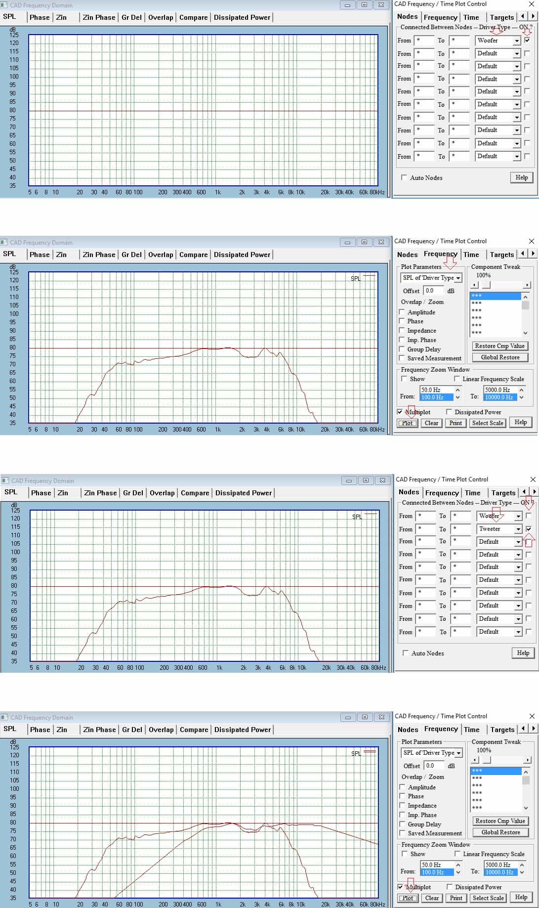
Judging from the graph, we have an overlap spanning from 1.5 kHz to 5 kHz. Consequently, a crossover point at 3 kHz should work nicely. A 2nd order filter will provide adequate protection for the tweeter. However, choosing it lower (2 kHz), might need a 4th order crossover. Anyway, we will fiddle around with the crossover point, but it will be mainly in the 2700 – 3000 Hz area. As you can see, there is a dip in both response at 2700 Hz. Maybe a Butterworth crossover will fix that since the responses will sum up with a +3 dB bump. More info about crossover types here. We will play around and see what works best.
Woofer crossover
We are going to start with a basic 2nd order Linkwitz-Riley low pass filter on the mid-bass. As for the crossover point, we’ll go for 2800 Hz, see how it turns out. We can use the built-in feature, to model the “textbook” crossover. This is done by pretending that the speaker is a resistor (fixed impedance value).
Close the windows and go to Crossover Tools -> Built-in Filter
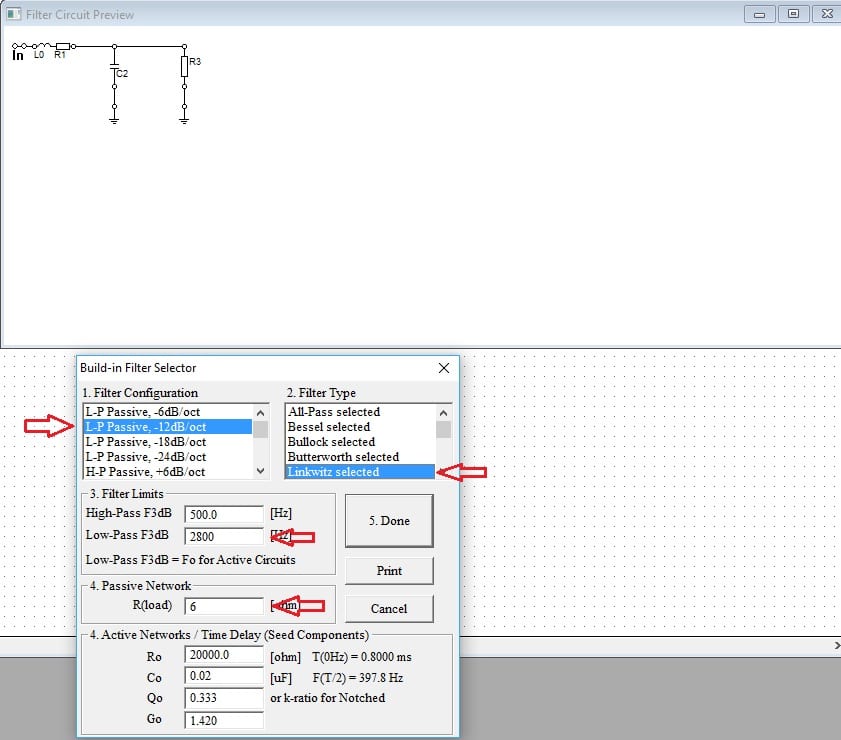
- Select 2nd order (12 dB / Octave) low pass.
- Linkwitz-Riley as crossover type.
- Crossover point at 2800 Hz.
- The impedance of the driver is 6 ohm.
Now click Done and click on the CAD sheet. The diagram should appear.

The resistor R3 is substituting the driver. In conclusion, we need to replace it with our SEAS driver.
- Click on the speaker icon.
- Click exactly over the resistor R3. This will replace the resistor with the speaker.
- Right click the speaker and associate with woofer SPL.

Now we got to check out what our SoundEasy crossover design did to the overall response (transfer function). Head back to Crossover design -> Frequency time domain.
- Make sure the Woofer is ON.
- Check the Auto Nodes function. This will assign the correct nodes for the woofer. The nodes are the little circles, marked with numbers, on the circuit diagram.
- Head to the Frequency tab. Then, from the drop down menu, select “Include Driver SPL”
- Click Plot. Maybe click Clear first if there are other graphs cluttering the sheet.
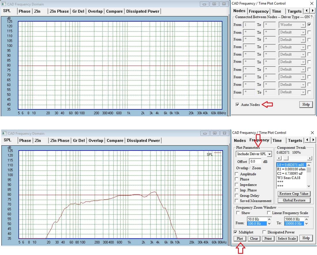
Looking at the graph might get you a little confused. It looks like nothing has happen. However, the crossover point is at 2.8 kHz. So, nothing happens till then. Furthermore, response peak at the end is due to baffle diffraction. But no worries we will try to optimize, see what we’ll get.
Optimization of woofer response
What this basically means is telling the application what you want. So, you got a capacitor and an inductor (2nd order topology) to work with. Your message to SoundEasy is : “Go ahead and alter their values until you get to the response I want”. This might be possible or might not. In either case, the SoundEasy crossover design will try to match your desired response as much as it can.
How to design loudspeakers - video courses


First of all, we need to define the desired frequency response. If we analyze the graph, the response starts to steadily rise from the 150 – 200 Hz point. What we want is a linear response starting with 150 Hz and then rolling off at 2800 Hz (the crossover point).
Go to Crossover Design -> Filter Crossover Optimizer and go to the Targets tab :
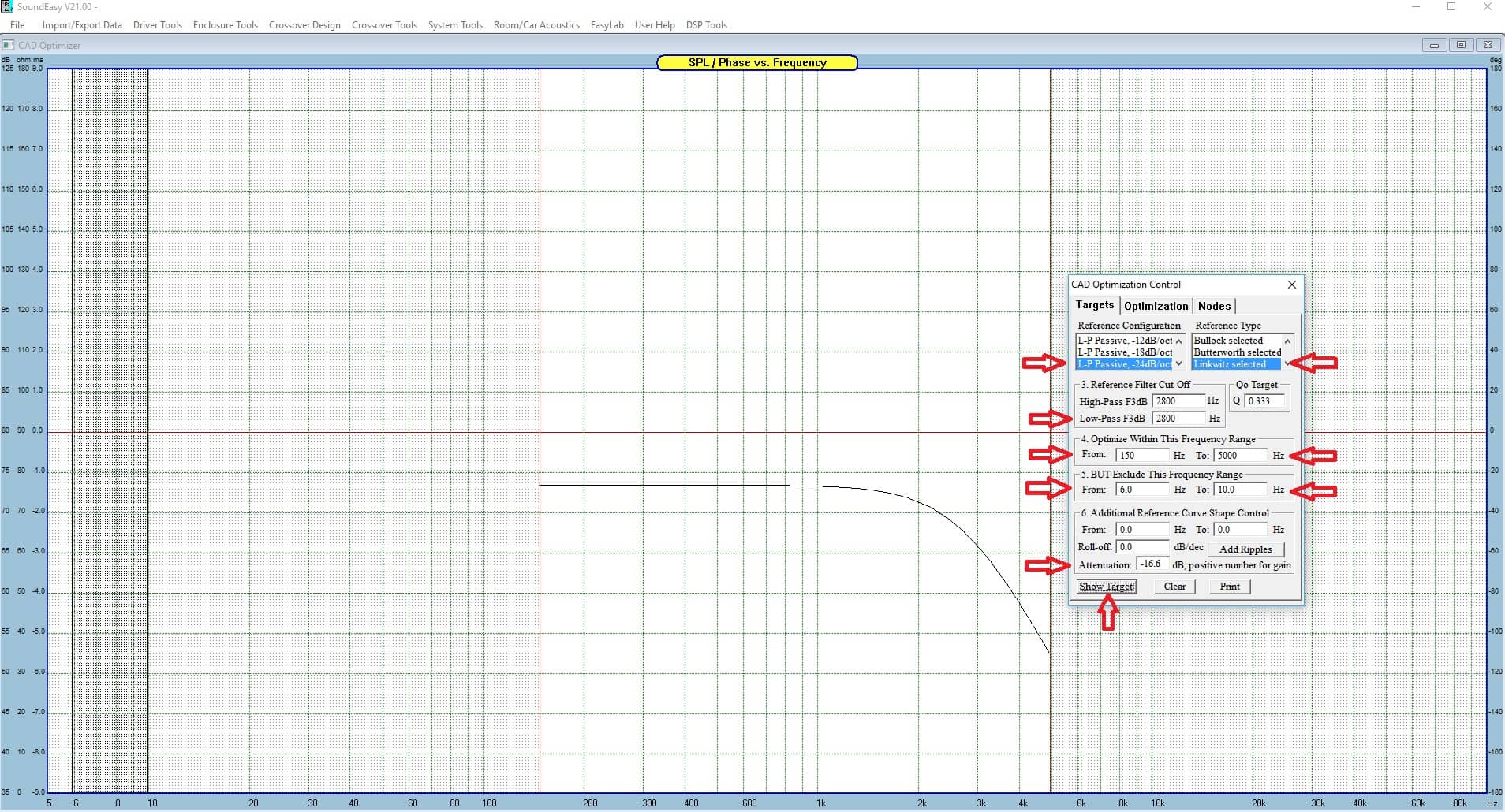
- Select 4th order Linkwitz-Riley. Although we have an electrical LR2 circuit, we are trying to reach the effect of LR4 acoustically.
- Crossover point at 2800 Hz.
- Optimize from 150 Hz till 5 kHz. The response starts to break linearity starting with 150 Hz. Don’t choose this point lower than the natural roll-off of the driver (50 Hz for example). The other end is usually double the crossover point, 5.6 kHz. However, it’s too close to the natural roll-off of the driver, so dial it down to 5 kHz.
- Exclude 6 Hz till 10 Hz.
- The attenuation is set depending on the SPL at 150 Hz, which is 73.4 dB. SoundEasy takes as reference 90 dB. In conclusion, we need to set the attenuation to -16.6 dB.
- Click Show Target.
Now go to the Optimization tab :
- Double click on each electrical component (capacitor, resistor, inductor), so they appear on the right column. R1 is the resistance of the inductor L0, so don’t include it.
- Click “Old Val”, so the present response appears on the graph.
- Click Optimize.

If you like the new response, click the “Accept New Values” button, to update the circuit with the optimized values. Finally, the response is much more linear. Since we got this far, now would be a good time to save the project.
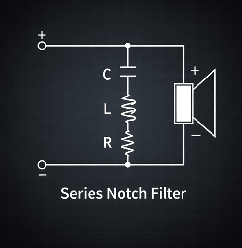
Tweeter crossover
To complete our SoundEasy crossover design, we need to address the tweeter response. Many of the steps that follow, we already made before, so we are going to skip the details. Just like before, create a Built-in Filter, but now go for high-pass 2nd order Linkwitz-Riley at 2.8 kHz. The resistance is now 3 ohms (the nominal impedance of the tweeter). Make sure the “Add” box is checked and click on the CAD sheet. The circuit for the tweeter should appear.

Now we have to use the CAD functions to manually apply some modification to the diagram :
- Merge the two diagrams so they share the same input.
- Add another resistor in series on the tweeter side. Most times the tweeter needs attenuation. Right click it and set its value to 1 ohm.
- Replace the resistor created by the Built-in Filter with a speaker, and assign the tweeter response to it.
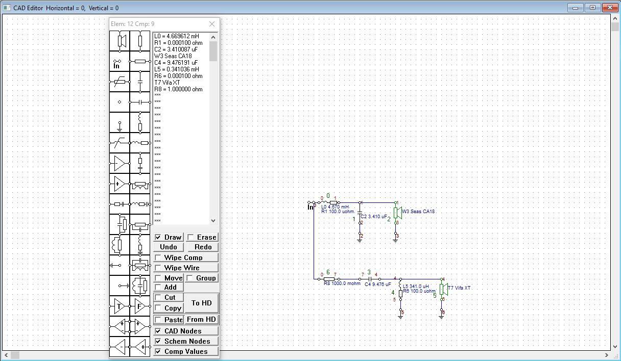
In the end it should look something like the circuit above. Then, we go to the “Frequency / Time Domain” section. On the “Nodes” tab deselect the woofer and check the tweeter. Finally, head over to the “Frequency” tab and plot the response, including the driver SPL.

Since the response clearly needs some optimization, we shall do just that.
Tweeter optimization
Just like with the woofer, go to the optimization section :
- Set for high-pass 4th order Linkwitz-Riley.
- Crossover point at 2800.
- Optimize from 1000 to 20000 Hz.
- The rest leave the same.

On the “Nodes” tab only the tweeter should be checked. Then, head over to the frequency tab and optimize the response. Of course, select only the components in the tweeter section.

The response after optimization isn’t that great. However, we can sum the response with that of the mid-bass and see how it looks like. First, accept the new values. After that, head over to the “Nodes” tab and check the woofer and the tweeter. Then, go back to the “Frequency” tab and click “Clear” and “Old Values”

Clearly the response is not linear. However, now it’s up to you to find a creative solution on how to make the response linear. I’ve done some tinkering to the tweeter side :
- Reduced the attenuation by 1 dB.
- Went for a 2nd order acoustic roll-off.
- Chose a Butterworth topology.
- Ran the optimization process again.
As a result, the tweeter response is looking a bit better and the summed response more linear.

The response looks much better now. However, it all comes down to your experience. You can implement all kinds of electrical circuits to resolve problems due to impedance or phase anomalies.
Conclusion
Our SoundEasy crossover design has gone pretty well. The response is quite linear, but it seems like there are some peaks and dips in the 2k – 4k area which are attributed to baffle diffraction. However, there are ways to minimize this, like placing the tweeter closer to the sides (not in the center). In conclusion, after several projects like this, some electrical engineering study and a keen eye for interpreting data, you can make a great SoundEasy crossover design.
References
- Image source : AI generated


Learn loudspeaker design from scratch

1 comment
That was a very nice tutorial. I purchased Soundeasy and tried to use it for a very long time. I finally sold it. I think I learned more in your article than all the time I had it. I might try it again. Thank you for sharing.