
DIY floor standing speakers – dual woofer – beginner friendly
Speaker plans for tower speakers
The point of this article is showing you how to make a pair of DIY floor standing speakers. The advantage of DIY is that you can tailor the speakers to your liking. Sometimes get it done cheaper, and of course you get the satisfaction that you have built something yourself. The main characteristics of this loudspeaker are the following :
- Low price. The loudspeaker uses budget drivers from Dayton Audio.
- Fun sound. This is not your audiophile grade speaker design. It has a linear sound for mids and highs. However, it also has a slight boost in bass. Who doesn’t love bass?
- Minimal crossover components to keep the cost, and build difficulty, down. 2nd order filters for each individual driver. An additional notch filter is used for the midrange.
- Flexibility. I give different build options to match your skill level. Also, the crossover features quick changes for different sound signatures.
In conclusion, I present to you a pair of cheap DIY floor standing speakers. The goal is to have a linear sound, down till the lower octaves. There, we will have a more pronounced bass. This is done by having a dual woofer setup. Furthermore, the crossover is designed with this in mind. If you fancy less bass and a more linear sound (on all the frequency bandwidth), a simple polarity switch will do the trick (more on that later).
Parts list
Here comes a long list of parts. This might not seem cheap after all, but bare in mind it’s a dual woofer tower speaker (how cheap can you go?). Sometimes I don’t find an exact match, in the link. I mention this, if it’s the case. However, the item in the link will get similar, if not identical results.
- Speakers (affiliate paid links) :
- Tweeter – Dayton Audio DC28F-8 – x 2 – [Amazon] [Sound Imports] [Parts Express]
- Midrange – Dayton Audio RS125-8 – x 2 – [Amazon] [Sound Imports] [Parts Express]
- Woofer – Dayton Audio SD215A-88 – x 4 – [Amazon] [Sound Imports] [Parts Express]
- Enclosure (affiliate paid links) :
- 18 mm MDF – [Amazon]
- Mineral wool – [Amazon]
- Dayton Audio binding posts – x 2 – [Amazon] [Sound Imports] [Parts Express]
- Bass reflex port:
- Jantzen audio 70 mm straight tube
- Inside flare
- Outside flare
- If you want to use a 3″ Precision port, take note that the cut-out will be different. You can keep the same length as the box it’s tuned too low anyway – [Amazon] [Sound Imports] [Parts Express]
Crossover parts
- Inductors (affiliate paid links):
- 4.7 mH, Iron core, 1.0 mm, 0.47 Ω – x 2 – [Sound Imports] [Parts Express]
- 3.5 mH, Iron core, 1.0 mm, 0.39 Ω – x 2 – [Sound Imports] [Parts Express]
- 0.60 mH, Air core, 1.0 mm, 0.37 Ω – x 2 – [Sound Imports] [Parts Express]
- 1.5 mH, Air core, 1.0 mm, 0.64 Ω – x 2 – [Sound Imports] [Parts Express]
- 0.27 mH, Air core, 1.0 mm, 0.23 Ω – x 2 – [Sound Imports] [Parts Express]
- Capacitors (affiliate paid links) :
- 100 uF electrolytic – x 2 – [Sound Imports] [Parts Express]
- 10 uF electrolytic – x 2 – [Sound Imports] [Parts Express]
- 56 uF film foil – x 2 – [Sound Imports] [Parts Express]
- 8.2 uF film foil – x 2 – [Sound Imports] [Parts Express]
- 12 uF film foil – x 2 – [Sound Imports] [Parts Express]
- 6.8 uF film foil – x 2 – [Sound Imports] [Parts Express]
- Resistors (affiliate paid links) :
- 1.5 Ω , 20 W – x 2 – [Sound Imports] [Parts Express]
- 3.3 Ω , 20 W – x 2 – [Sound Imports] [Parts Express]
- 8.0 Ω , 20 W – x 2 – [Sound Imports] [Parts Express]
Of course, you will need wires, and a board for the crossover circuit, but that is at your discretion.
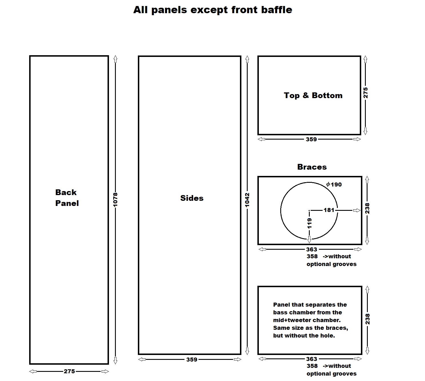
Panel dimensions
The material I’m using is 18 mm thick MDF. So, when I’m going to list the panel dimensions, you will only see length and width. These are the sizes you need to cut :
- 1078 x 275 mm (front and back) -> 6 pieces
- 1042 x 359 mm (sides) -> 4 pieces
- 359 x 275 mm (top and bottom) -> 4 pieces
- 363 x 238 mm (internal braces) -> 6 pieces
- 358 x 238 mm (if you don’t want to make grooves for the braces)
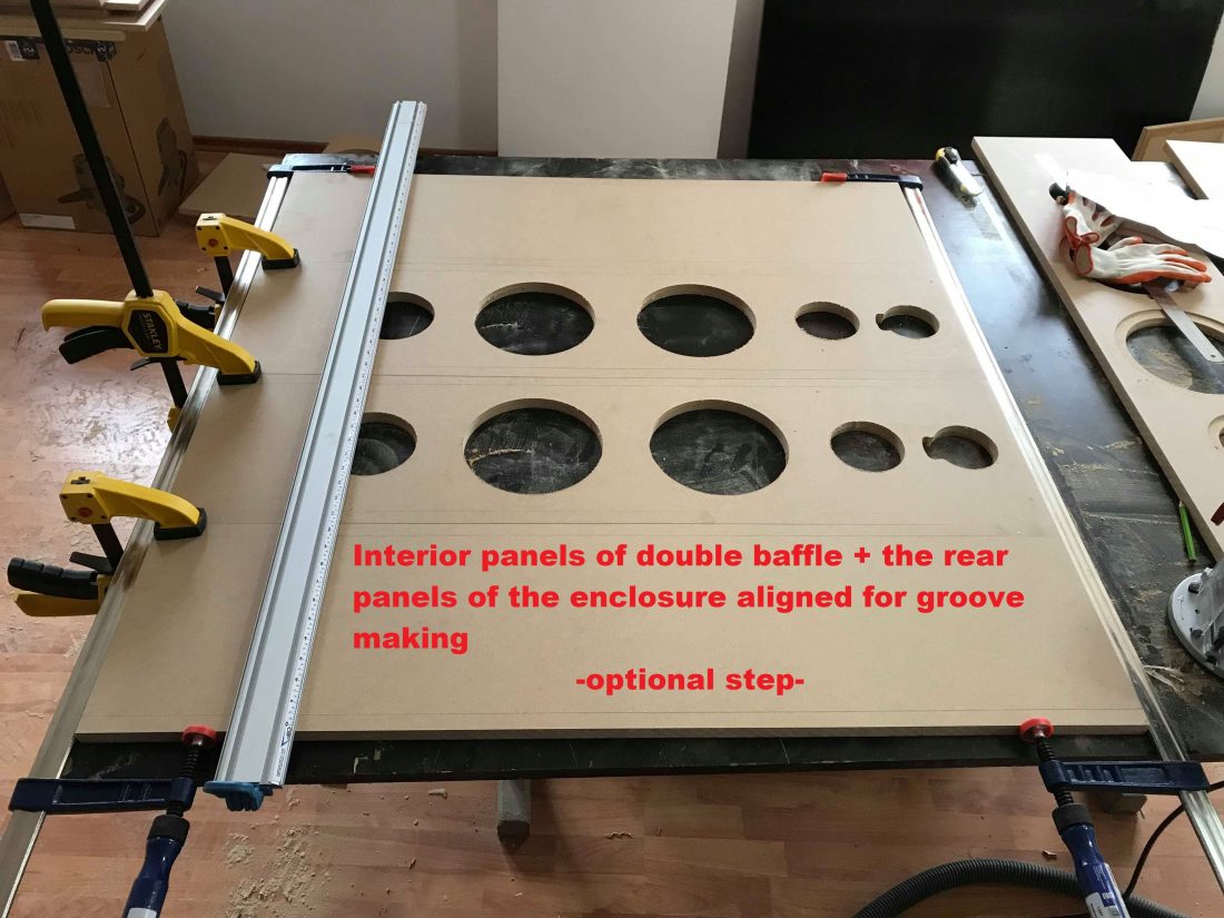
Here is a visual representation of the front baffle :

Just above we have the front baffle of our DIY floor standing speakers. The first sketch from the left, just shows the center of the circles. And since we have a double baffle (2 panels glued together), for added stiffness, we have 2 additional sketches. The rear part of the baffle contains 3 mm deep grooves to fit the braces. If you feel this is too much for you, or you don’t have the necessary tools, you can make the braces shorter and skip the groove process.

The rest of the panels are self explanatory. Just cut a big circle into the braces, so air can circulate. Do this for all the braces, except for 2. You need a panel to separate the chamber with the bass from the chamber housing the mid + tweeter. As a result, make sure you don’t cut a hole in all of them (just 4).
DIY floor standing speakers build
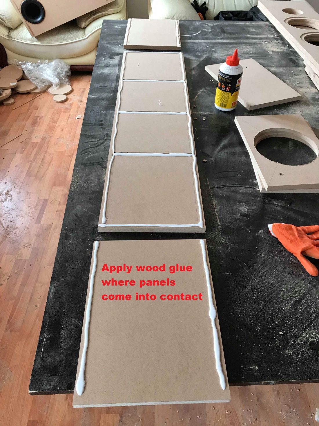
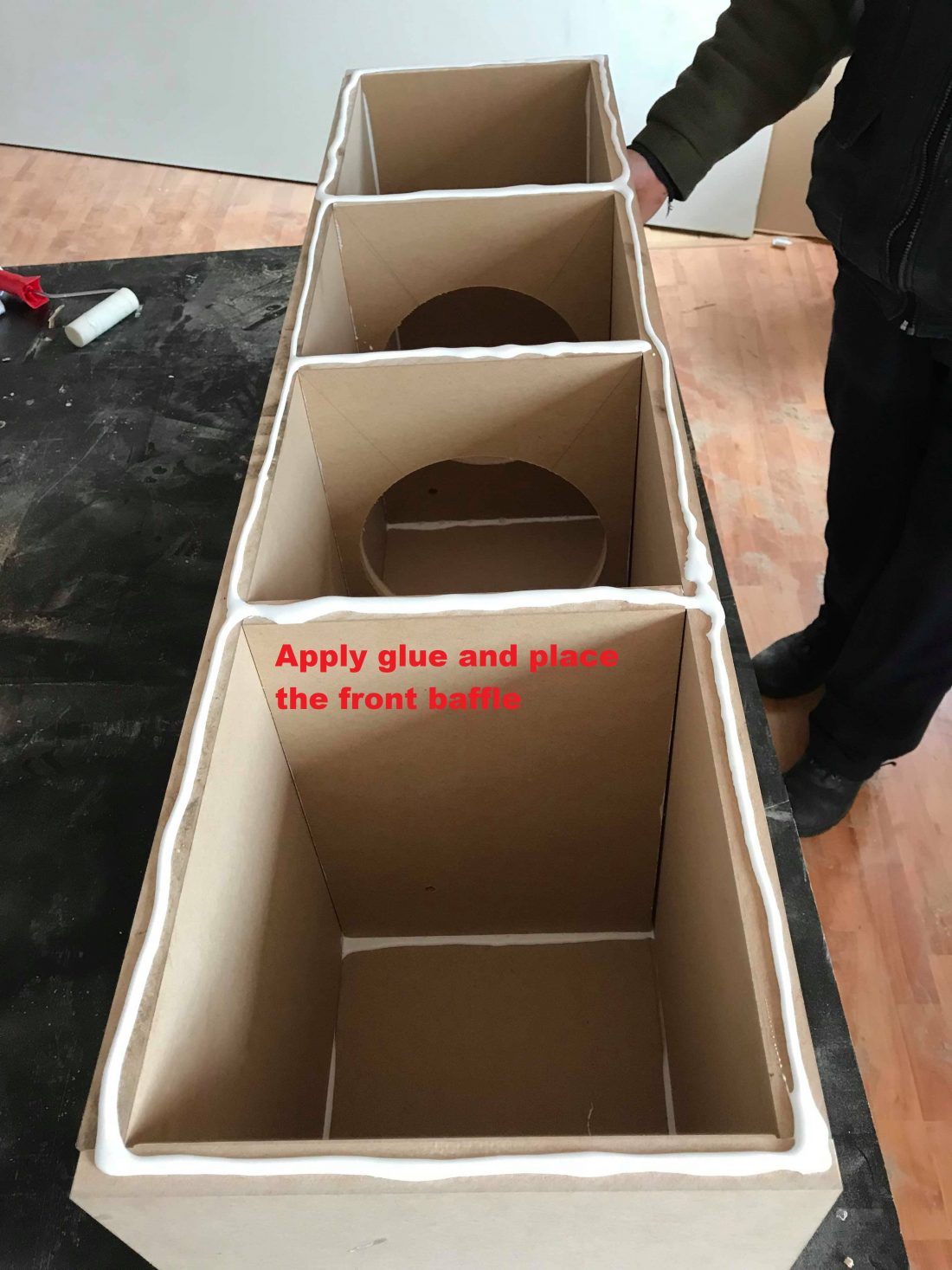
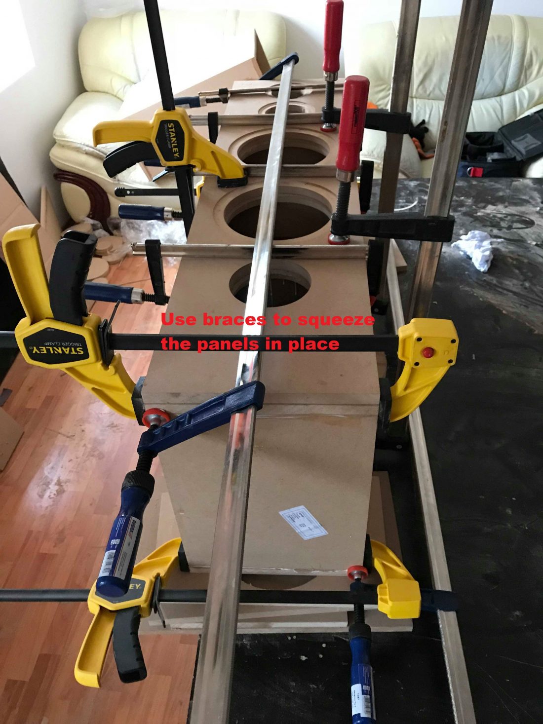
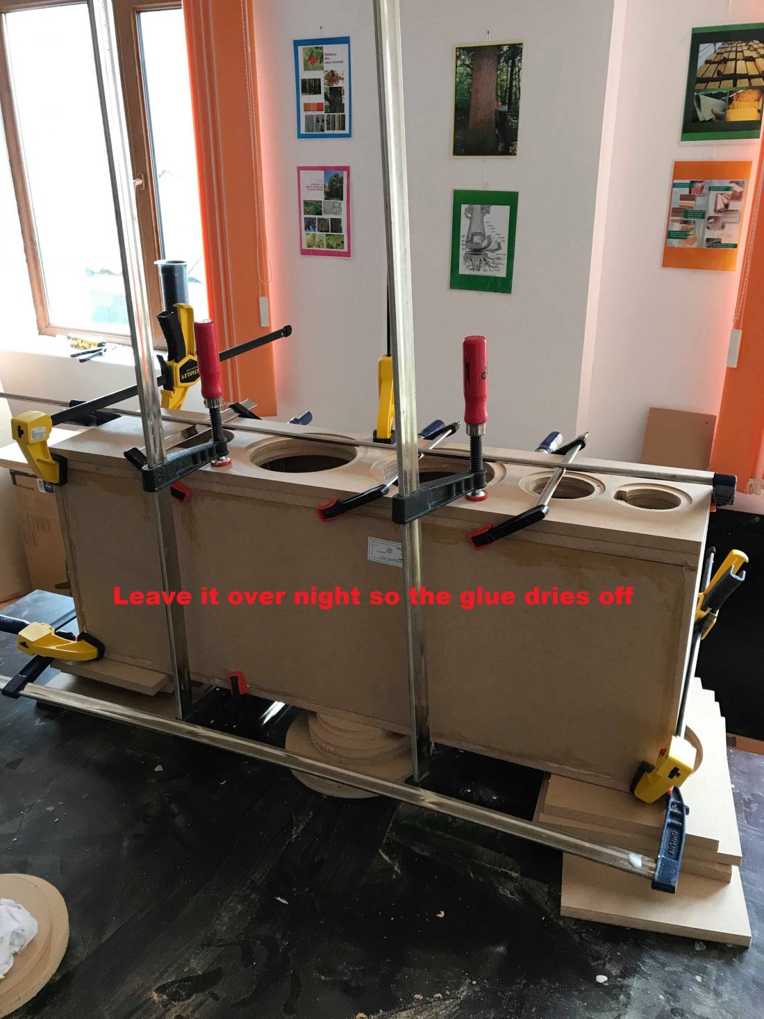
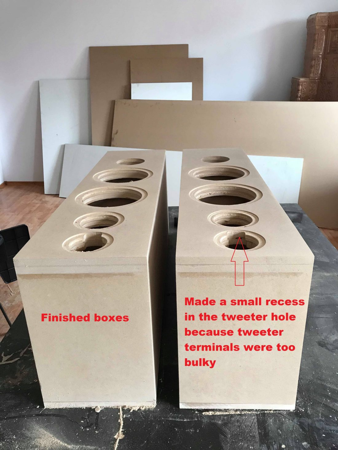
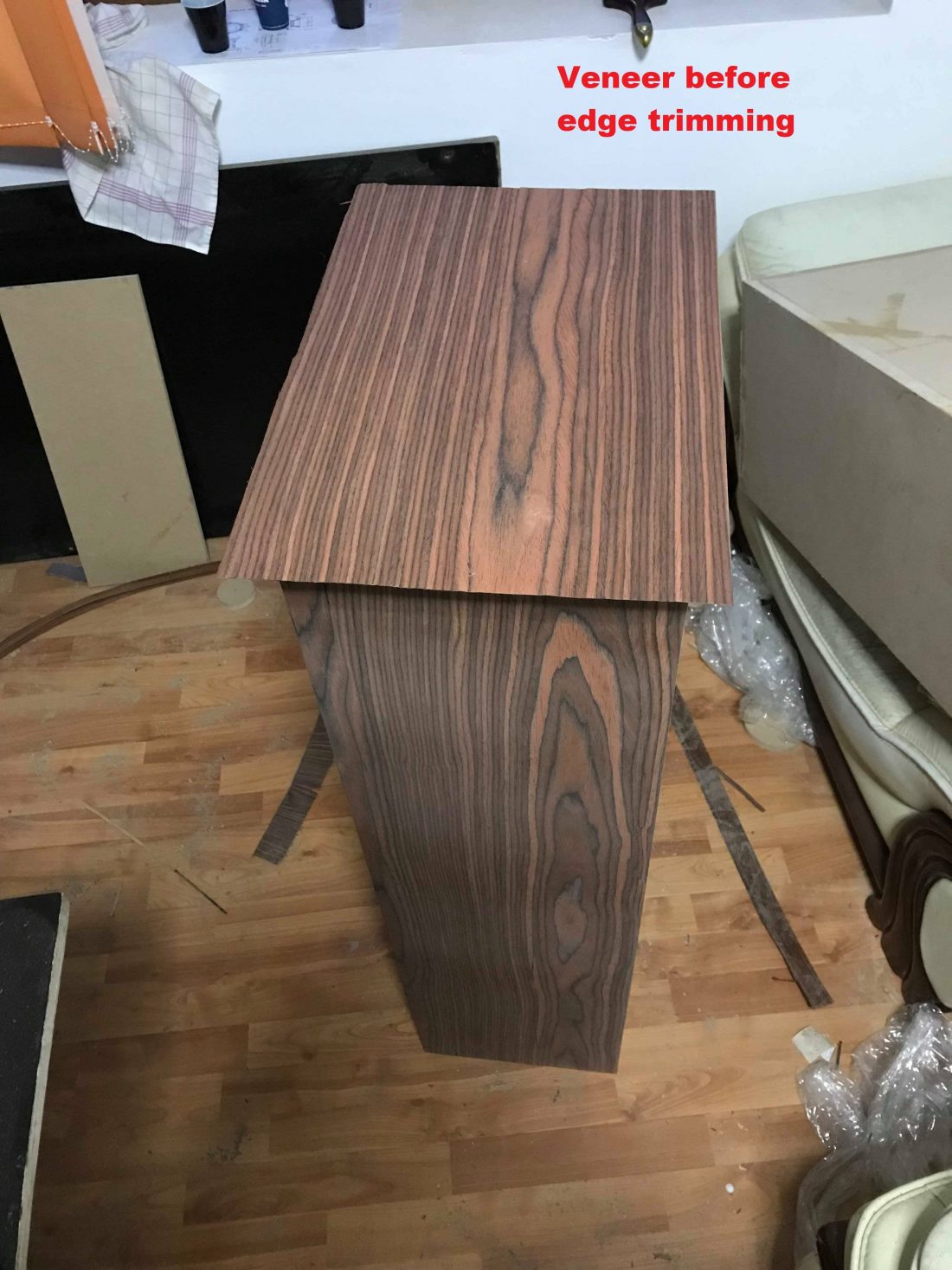
Here are some pictures with the actual build :


Above, you can see the baffle. It’s made by 2 boards glued to one another. The surface panel has the recessed steps for the driver cutouts. This way the speakers are mounted flush with the baffle. The 2nd panel has simple circle cutouts.
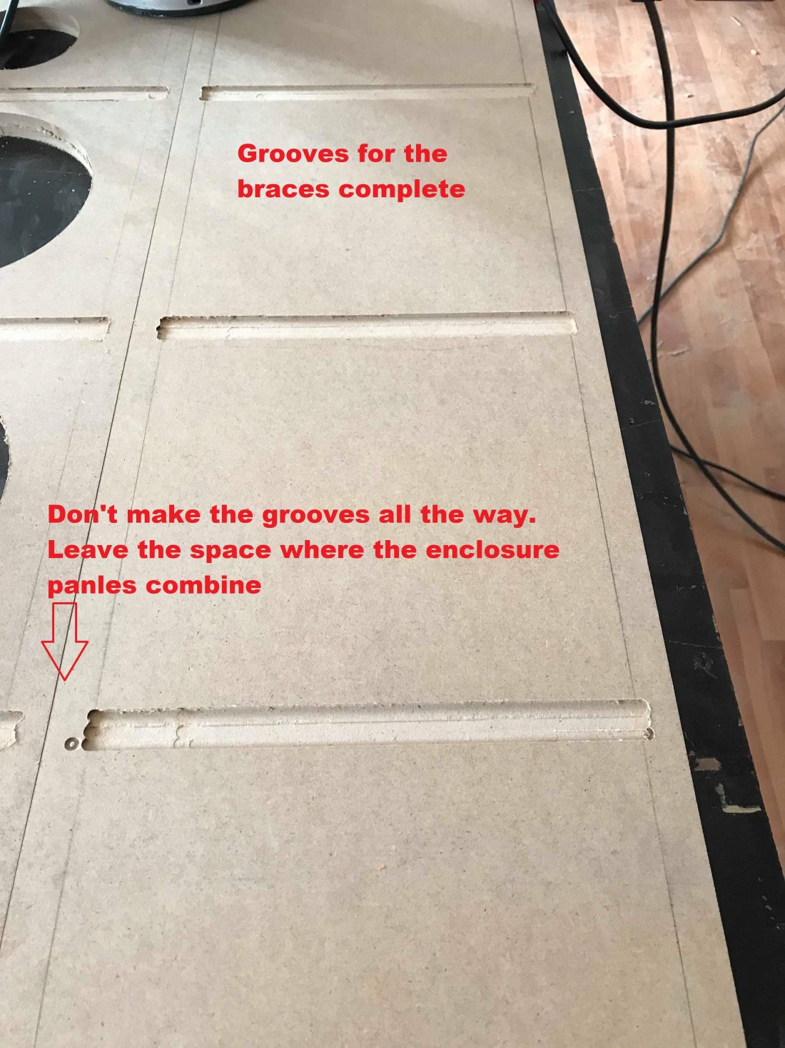
The grooves are 3 mm deep. Their purpose is to make a nice fit for the braces. Place them on the front and rear panel. When I say front panel, I mean the interior panel of the double baffle. For this job an Emerson tool and router is an excellent choice. Align all the 4 panels which need grooving, so you make the grooves in the same spots. Leave the extremities of the panels untouched (18 mm on each side). That’s where the panels fit together, and you don’t want holes there.
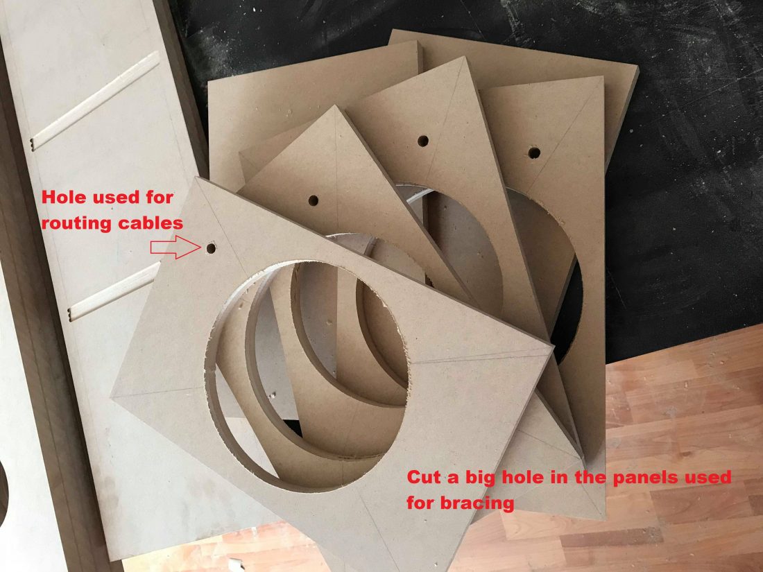
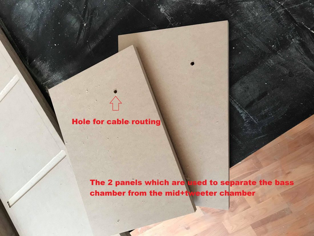
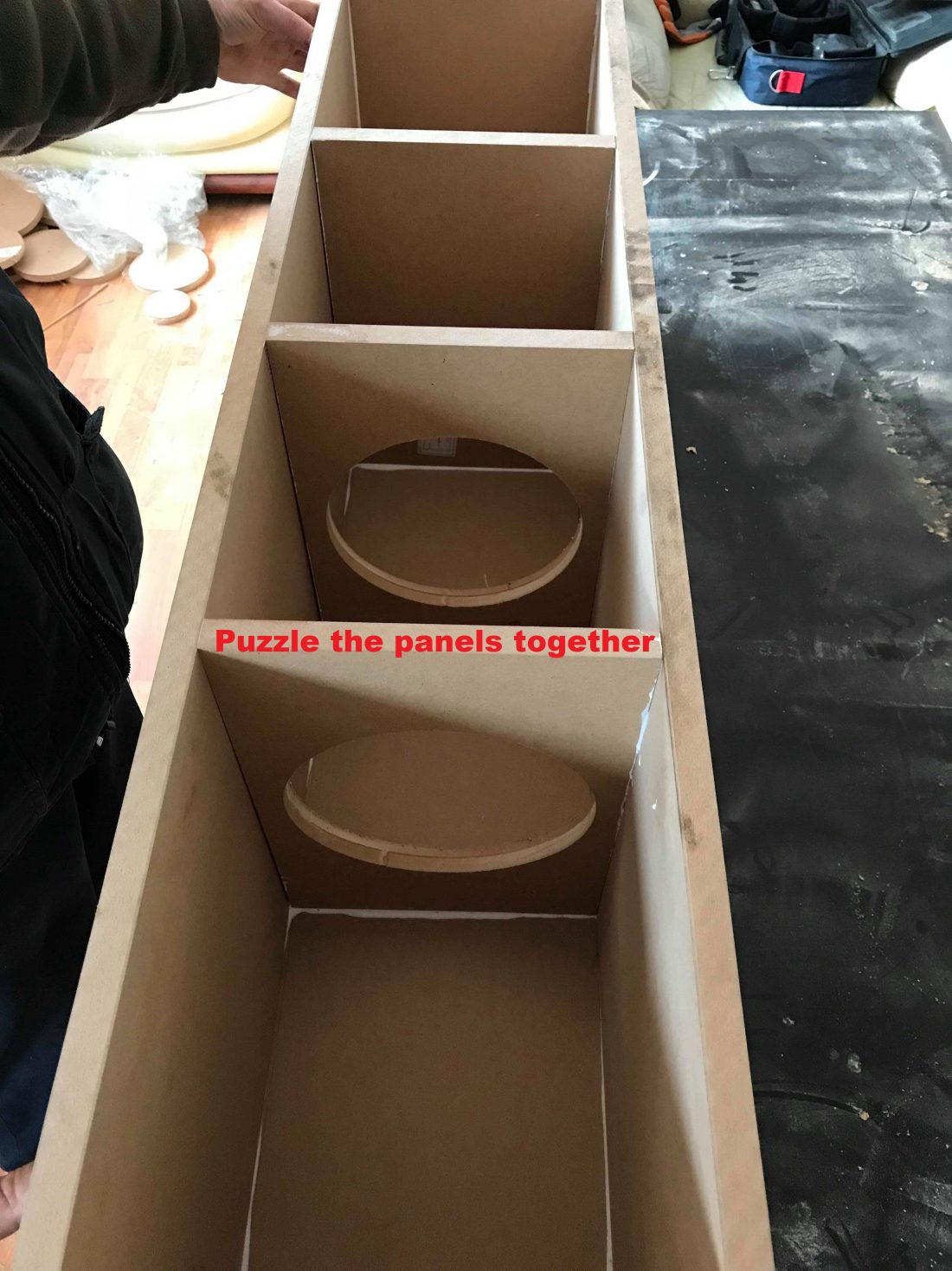
Above, you have the 6 panels used for bracing (3 for each of the DIY floor standing speakers). Leave 2 of them untouched. Just drill a small hole through them, so you can route the cables from the tweeter and mid-bass to the crossover. For the rest (4 pieces) of the panels, make a large hole in them. Even though you can find the exact diameter in the schematic at the beginning of the article, the exact size of the circle doesn’t matter.

I’m sure you find the pictures above self explanatory. As a finish, I applied 0.8 mm rosewood veneer using contact adhesive.
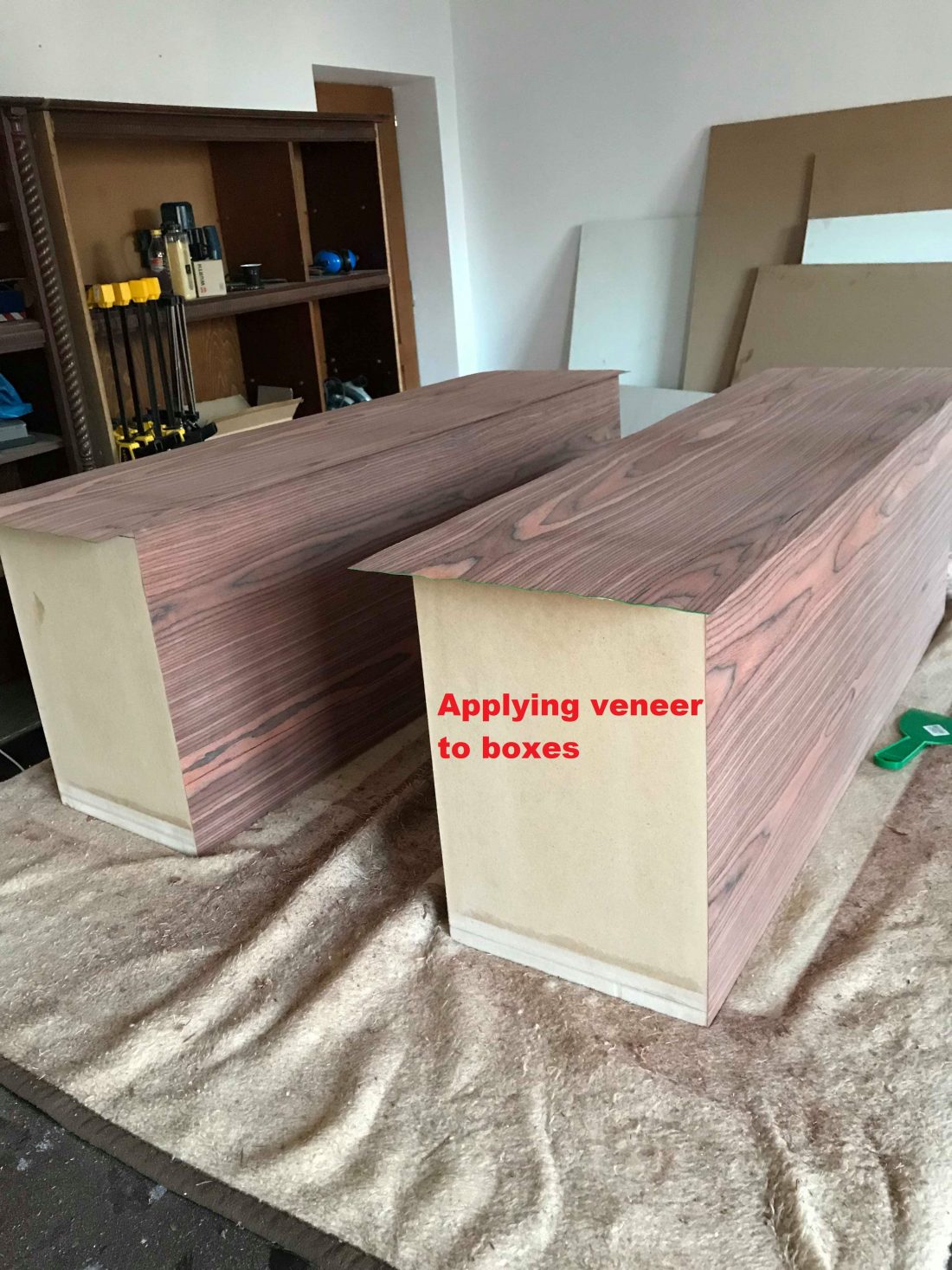

First time that I finished a box in veneer. However, I’m quite happy with the result. Next time I’m confident I will do it even better.
Sound damping
I consider sound damping material to be optional, especially in a bass reflex enclosure. However, acoustic measurements revealed a standing wave. A nice way to eliminate it is to use mineral wool.

Use 5 cm mineral wool on sides and top. For the bottom, use 3 layers of 5 cm (15 cm thick pad). You can check out more details in this article.
Port tuning frequency
The port design that I will describe in just a bit, is for a 25 Hz tuning frequency. Some might consider it too low, and I won’t disagree. However, this type of tuning has its advantages. I, myself, aimed for a higher tuning frequency, but it seems I miscalculated something and I ended up with a lower box resonant frequency. Since I ended up here, I decided to leave the port like this. The advantages of tuning this low are the following :
- Better bass response below the resonant frequency of the driver.
- Smoother roll-off. In conclusion, better transient response.
- Less port noise. The driver cannot play efficiently under its resonant frequency. Therefore, there is less amount of air movement through the port. As a result, less air turbulence.
- “Subsonic” acoustic filter. Since the port takes the load of the speaker at that particular frequency, it makes sure it doesn’t crack down under the pressure of low octave tones.
Even though you have these advantages, having a higher tuning frequency, translates in a better bass response in an area which you will encounter on music more often (30-40 Hz). Not many tracks go under 30 Hz. But anyway, here are my port dimensions :
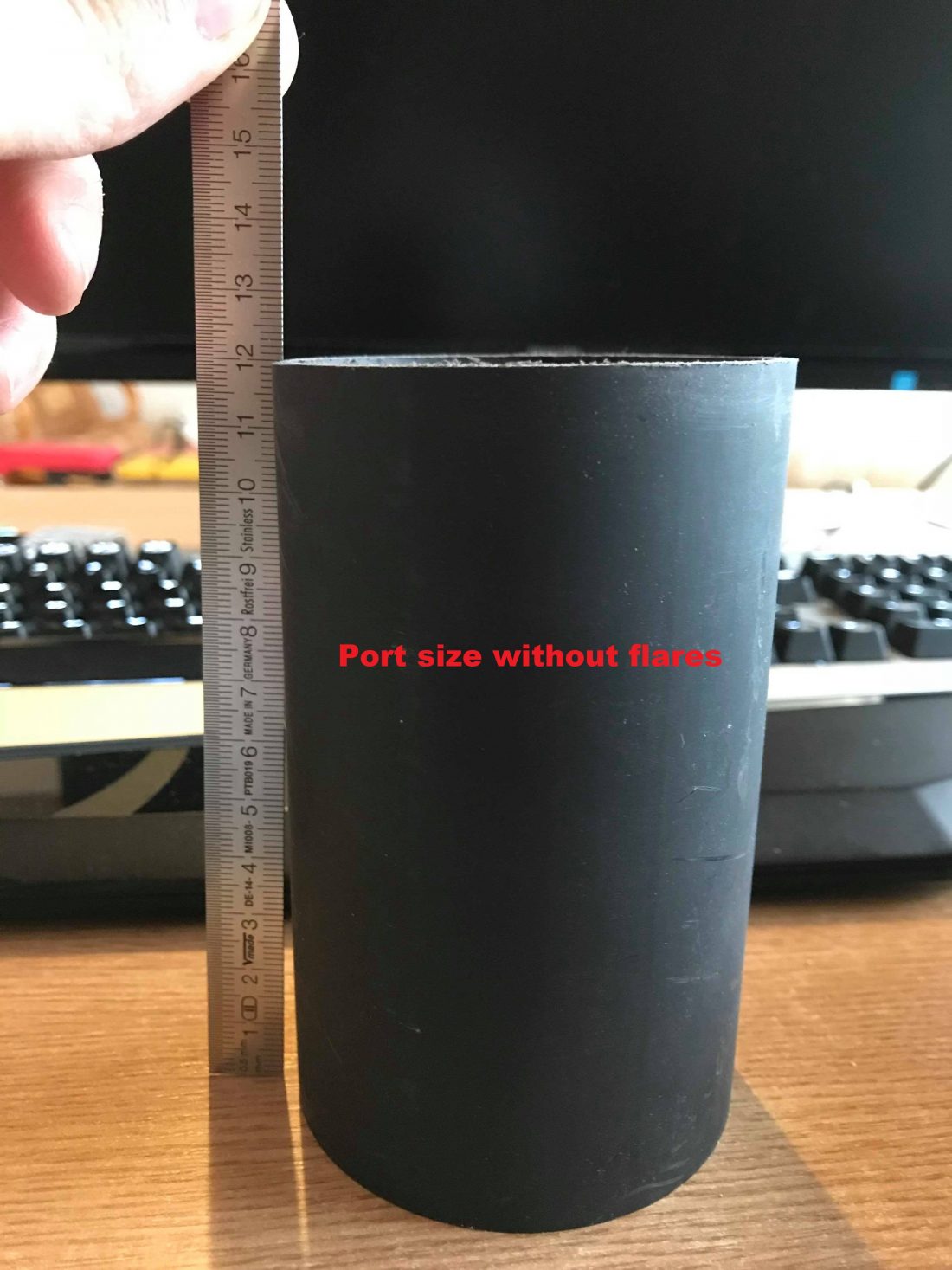
The Jantzen Audio port I used in 70 mm in diameter. The length is :
- 120 mm without flares.
- 190 mm with flares.
If you use the 3″ Precision port, that is 75 mm in diameter. As a result, if you use the same dimensions as I did, you will get a higher tuning frequency (because the diameter is a tad larger and the length is the same). If you keep shortening the port, you will get an even higher tuning frequency. Expect more air turbulence when going up in tuning frequency. However, the larger diameter helps in this regard.
Crossover design
To finish our DIY floor standing speakers, we need to get into the actual crossover design. First of all, let’s talk about how to wire the bass speakers. Some might have issues here because the woofers are dual voice coil, and this might confuse someone.

Basically, you wire the coils in parallel and the 2 woofers in series. For a total of 8 Ohm load. Now let’s take a look at the actual crossover diagram :
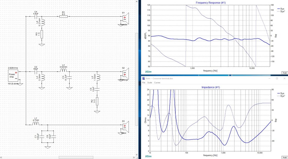
Here is a brief descriptions of the crossover :
- on each speaker side there is 2nd order filter.
- the midrange has an extra notch filter. The response has a peak at around 1200 Hz. This is probably caused by edge diffraction. You could probably solve this issue by rounding up the edges and by placing the midrange and the tweeter off-set on the baffle (not in the center). However, this is not tested by me.
- Tweeter has an attenuation resistor.
- The capacitors on the woofer side are electrolytic. This is to keep costs down because an 100 uF cap is expensive. I wired 2 capacitors in parallel for a total of 110 uF. I did this because it’s hard to find a 110 uF cap. Furthermore, electrolytic capacitors have low power handling, and by wiring them in parallel, you basically double the power they can take.
- Big value inductors are iron-core, to keep the cost down. Furthermore, iron-cores have lower resistance to the equivalent air-core. As a result, L1 has lower resistance, and therefore more bass for the woofers. However, resistance of L2 is quite irrelevant.
Crossover tweaks
What is a pair of DIY floor standing speakers without tinkering? There are certain tweaks that can be made to this crossover, depending on your preference.
If you want less bass and a more linear sound, you can simply swap the polarity of the woofers (either in the crossover or where you connect the bass speakers). The crossover is designed with a bump in low frequency response. Fortunately, I noticed if I switch the polarity of the woofer(s), the response flattens on the bass side. I did not calculate this, it’s just a fortunate coincidence. If this is your cup of tea, make the change.
Another thing that might be relevant is the dip in impedance at around 1200 Hz. This is created by the notch filter to fix the peak in frequency response at 1.2 kHz. Problem is that it’s getting closer to 2 Ohms. Many amplifiers cannot handle 2 Ohms. However, since it’s such a narrow bandwidth and pretty high in frequency, most amplifiers should handle this hiccup, no problem.
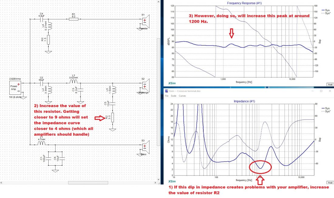
If you have a really crappy amplifier, it might shut off because of this. Simply increase the value of the resistor R2 until the problem goes away. As the resistor reaches 9 Ohms, the impedance curve doesn’t dip below 4 Ohms and problem should be solved. However, as you increase the value of the resistor, the peak in frequency response gets larger and larger (and ruins linearity). Anyway, most amplifiers will not have any issues here.
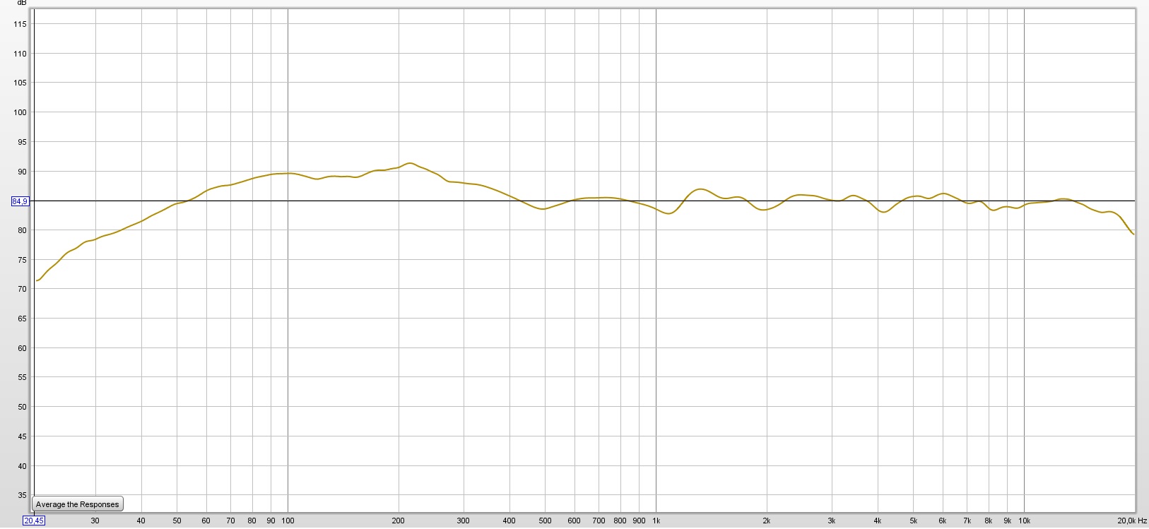
Frequency response
In the crossover design app you see the response only down to 200 Hz. This is because I used only far field measurements to model the crossover. However, after the speaker was finished, I included the nearfield measurements as well, to have a full frequency response measurement.
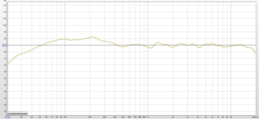
So this is how the response of our DIY floor standing speakers looks like. It’s without the inverted polarity of the woofer, so with a bass boost. As you can see. it has a linear midrange and top end. The lower octaves are higher in amplitude. You can also see the effect of low port tuning. The roll off is very smooth and still hits very low frequencies with decent output.
Conclusion
First of all, here is a picture with our finished DIY floor standing speakers :

Once again, I want to iterate that this not your audiophile pair of speakers. As a result, they are designed to give a fun sound, with above average bass response. They have physical presence in a room and look awesome with their dual woofer setup. Hopefully, this pair of DIY floor standing speakers will have a low build difficulty, as I mention in the beginning. Bare in mind, that these are tower speakers, and inherently are more difficult to build compared to a pair of bookshelf speakers.


Learn loudspeaker design from scratch

45 comments
Marius, could you write a follow-up article that goes into more detail about the measuring of the drivers and crossover simulation. I’m especially interesting in mic positions and how you measured the dual woofers + port, etc.
To measure the dual woofers + port you have to do the following:
1) Nearfield measurement of one bass driver.
2) Add +6 dB to that curve (because you have 2 drivers). You can make 2 individual measurements and add them up, but you will get the same result.
3) Nearfield measurement of the port.
4) Adjust the port level according to its size, and the size of the woofer(s).
5) Combine the 2 curves (speaker nearfield +6 dB and the scaled port nearfield).
6) Apply box diffraction function to the resulting curve.
7) Take a far-field measurement.
8) Scale the nearfield measurement from point 6) to far field.
9) Splice the 2 curves (near field and far field) at the correct spot and there you have it.
If you have any questions about these processes, please read this first : https://audiojudgement.com/quasi-anechoic-loudspeaker-measurements/
What effect does that much mineral wool have on the effective volume of the box?
Mineral wool, while denser that other dampening materials, won’t have much of an impact on enclosure volume.
False. It lightens quick heavy to deeper smoother sound in most cases in my opinion.
Hi Marius, I really enjoyed your DIY dual woofer floor standing loudspeaker article and although you stressed multiple times that they were not audiophile grade, I’m wondering what you would suggest or do to get them closer to the audiophile target? Would tailoring the cabinet for flatter response be closer to the target?
Thanks and have a great day!
Chris
The fact of the matter is that you can get the response flatter by reversing the polarity of the woofers in the crossover. That is not the main problem. The drivers are not phase aligned correctly. This might be a problem for some. To do so, the crossover would get very complicated and raise the price too much. We are using cheap drivers after all. The woofers have some weird basket resonance (my guess is because of the low quality stamped frame). It’s not very apparent, but can be detected on certain music on specific parts. For this reason I consider them to be usable only from a fun, warm sound and not so much as a critical listening device.
Could wrap the baskets with butyl rubber tape. Worked very well on an old sub i had laying around once. Cheap so worth a shot perhaps.
Send me a picture of Circuit diagram
It’s in the article. You can save that picture directly.
Hi, thank you very much for this demonstration, I’m planing on doing my own diy 3way speakers, the same as the one you made, I’m very inspired, thank you very much…..
Regards
Neville
How did you handle the issue of midrange driver being overpowered by the woofers?
I was thinking you were going to do a box for the midrange. I was hoping to learn how to size the box.
Well this is one of the key aspects of the system : to have big bass. That fact that they are overpowering the midrange is not an issue. If you want linear sound, you can use an attenuation l-pad on the woofer to lower their output. And in our case, with this crossover, inverting the phase of the woofers simply makes the sound more linear and blends better with the midrange (lower bass output).
Well, first of all, there was the standing wave issue, which was somewhere in the 100 Hz area. I made an article of how to kill that standing wave with dampening material. Should be linked here. Secondly, there was in fact a basket resonance for the woofer. Only on certain tracks, with that particular frequency, and no other extra loud sounds, you could clearly hear it. I did a test, where I took one driver out so I can fit my hands through the hole and grab the second speaker from the back. On the same track, if I firmly pulled the back of the speaker (which was still mounted to the enclosure). When I did this, the ringing would go away. I tried every modification possible to the enclosure (sanding everything up, using different gaskets, larger screws) with no success. My conclusion is that the enclosure was fine, but the speaker basket was poor quality. Stamped frame doesn’t mean it should be low quality, but this one clearly wasn’t a good egg. Overall it sounds good, but on select few tracks, you can hear the ring and it’s annoying. If you can fork out the cash, I would definitely encourage you to buy the seas speakers. Cast frame of way better quality, plus the speaker itself is in another league.
Can you please share the crossover design and diagram also …. it will helpfull for us……
You can find the diagram in the article
Send me picture of crossover please, and link of iron core inductor seems broken.
Here is a pic of the crossover board :
If the link is broken, just use an inductor with the same values. It doesn’t have to be the one in the link.
It’s quite hard find the same values on Italian web shop, because I can’t find anything (drivers and components) on Amazon or somethings like that.
Is there a tollerance for ohm values? L values it’s easy to find. Not same for ohms.
Thanks for patience.
Thanks so much for your suggests! I found all components on http://www.soundimports.eu but there are little differences:
inductors
4.7 mH, Iron core, 1.0 mm, 0.47 Ω
3.3 mH, Iron core, 1.45 mm, 0.19 Ω
0.60 mH, Air core, 1.6 mm, 0.19 Ω
1.5 mH, Air core, 1.0 mm, 0.62 Ω
i mainly followed L Values ( does it correct) ? because there isn’t AWG17
resistors :
are 20W only, not 25W
That’s should be correct ?
Thanks.
Alessandro
yeah you should be fine with those.
Hey just curious what your crossover points ended up being? Your build looks awesome!
It’s at 400 Hz and 3.3 kHz
Great article, thank you very much. I am a total noob when it comes to the actual technical aspects as far as the tuning goes. Pretty much just build boxes that appeal to me and don’t spend much time on the tech specs of fine tuning. Yes I know all my builds are probably muddy crap but Im not an audiophile by any means.
If anyone is looking for speaker repair parts / drivers then have a look at : https://www.parts-express.com (pretty sure they ship globally)
No I don’t work there or get paid by them, I just stumbled on to their site looking for my drivers etc….and figured I would share!
DIY noob here
Can you please discuss the role of MTM arrangement in this set up.
This is not an MTM arrangement
what is a pic of the crossover board :
Hi,the sub portion represents how much volume?
If the front of the box would have been slanted ( in an angle) would that have eliminated the standing wave?
Thanks
That would most likely help, yeah. But the crossover needs to be different as the acoustical centers of the speakers will change.
Ok good point, what about the volume for the bass section? Thanks
48 liters
Ok thanks…i tried to estimate based on the dimensions and had approx 60 liters…so thanks again..
67 liters is the external volume, so don’t get them confused. 48 liters is the internal volume.
Thanks…
Hi again, i am curious to know if you used your Xcel spreadsheet or the low cost app for the design of the bass section? Thanks
I used WInISD to model the enclosure response. If you are talking about Subwoofer design toolbox, I don’t use that app. It’s nice, lightweight and easy to use. It’s awesome for beginners. Also, it quickly calculates the panel dimensions of the box, which is super useful. Other then that, I prefer WinISD as it has more options. However, when it comes to the excel spreadsheet I still use it a lot. Because it’s super fast. When I am searching for a particular driver, I just open the spreadsheet punch in 3 values and then I can get an idea of how large the box needs to be.
Ok thanks, i have the WinISD and also use the Excel like you to give an idea of the box…btw your courses are very interesting and you add value on top of the theory…
Hi Marius,
I am in the process of starting the building of this speaker and have a few questions:
For the grooves you mention 3mm in each panel witch gives a panel of 363 mm and without 358mm witch is 5mm, discrepancy?
The bass volume is 48l, is this net ie total volume would add the speakers and port and brace volumes?
I will probably change the bass speakers for upgraded Dayton Audio ,do you think that existing mid and tweeter can be consider HF?
Thanks
Marius,
I’d love to build these but am a complete idiot when it comes to making and assembling crossovers. Would you be interested in building a pair of crossovers that I could purchase off of you so I can build these?
No, sorry, I don’t offer such services.
Hello Marius,
Thank you for the proffessional content. I am very new to the audio world and can´t help wondering what might similar speakers cost today online? Your project parts cost around 700€ plus MDF and paint etc. Do you have any guess regarding this matter?
I am really interested in this DIY project and made some 3D modelling based on your plans (we have only 19mm MDF available in Estonia), I wonder why you didn´t round the edges of the front baffle?
BR,
Rainer
This set of speakers is quite large, and with a heavy bass response. So, you might consider them more like a fun speaker rather than something audiophile. If you compare them with off-the-shelf already made loudspeakers, you might get better deals in a shop. Mass produced speakers are most likely cheaper than DIY variant, so don’t expect better value in DIY projects. The edges are not rounded because I used veneer as a finish. Veneering round edges is rather difficult.
Appreciate the write up, ive just completed this build and other that the woofer change is there any other suggestions on potentially boosting the mid to high range, I will be adding a sunflower centre speakers also.
Can flick you some pictures if you like also to add to the log
DIY floor standing speakers build Do u sell it?