
DIY speaker plans – 2 way bookshelf kit
How to build a speaker cabinet
In this article we will cover how to make a 2 way bookshelf speaker, with full DIY speaker plans, all the components and tools you need. Furthermore, we will touch some of the designing concepts behind our build as well. It’s nice to follow a list and build something, but it’s a whole another thing when you understand some of the principles behind the process. For our project, we will be using the following drivers (affiliate paid links) :
- Peerless XT25TG30-04 – tweeter (Amazon) (Sound Imports)
- SEAS CA 18 RNX – mid-bass (Amazon) (Sound Imports)
The drivers are not expensive, nor cheap. However, if you sum up all components, it does add up to a respectable price tag. So make sure you do your best when building this loudspeaker.
Designing the enclosure
To improve the lower end response, the enclosure will be a bass-reflex design. I measured the T/S parameters of my particular driver and after a quick look at the alignments table, I concluded the following specs for the enclosure :
- 10.15 liter enclosure tuned at 48 Hz, for a maximally flat Butterworth response.
Now, this is all fine and dandy on paper. However, you are going to have a bad time if you want to fit a decent size port inside of the cabinet. In conclusion, we need to increase the volume and alter the tuning frequency, so we get a decent curve. Second iteration :
- 15 liter enclosure tuned at 50 Hz.

15 liters should be enough size for everything that we need to fit in the box. Furthermore, making the box bigger will demand a shorter port, so even easier to fit. Regarding the frequency response, you can see from the graph above, that the linearity has suffered almost negligibly, and we gained a slight low end boost. We are going to use a 2″ port flared at both ends. To reach our tuning frequency the port needs to be 120 mm long.
Out of laziness, I didn’t cut any of the port’s tubing to length. The port is made out of 2 flares, 2 connection rings, and a long pipe. Simply remove the pipe and one connection ring and fuse the 2 flares together using the other connection ring. The port is now 125 mm (including the flares, which is actually less than 120 if you discount part of the flares) and the tuning frequency shifted to 53 Hz. I’m quite fine with that also, it will bring a bit more punch to the overall sound. The box dimensions remain as calculated before.
Box volume
Before we start writing our DIY speaker plans, we need to take into consideration that 15 is the net volume. Consequently, we need to add all the components which go inside the box and take out space (volume).
- Net volume : 15 liters.
- Port : 0.25 liters.
- Speaker : 0.35 liters
- Crossover : 0.2 liters
- Bracing : 0.4 liters
- Total volume : 16.2 Liters
DIY speaker plans – cabinet design
For our cabinet we will use 18 mm MDF (1 mm less than standard 3/4″, but that is what I had lying around). To have a baffle with good proportions and enough room to fit the port in the back panel, here are the panels which are needed :
- 340 x 227 mm (2 pieces).
- 280 x 227 mm (2 pieces).
- 280 x 304 mm (2 pieces).
- 191 x 280 mm (1 piece) – Bracing.
Multiply all these by 2, because we need 2 speaker boxes.
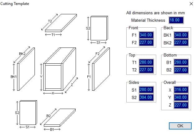
Just above, you can see an expanded view of enclosure panels, so you can get a better idea how it all fits together.
Baffle diffraction
You might think that placing the speakers is a straightforward thing to do. However, we can reduce diffraction problems if we offset the tweeter. Normally you would place the speakers in the middle of the baffle, because it looks symmetrical. Let’s see the effects of diffraction from our tweeter, on our baffle :

There is valuable information in the graph above. Focus on the 2 kHz – 4 kHz area. This is the frequency band where the mid-bass and the tweeter will combine their responses. If both are in the middle of the baffle, they will have similar diffraction, and the diffraction effect will basically double up. In conclusion, the overall frequency response will have a big dip at 2-3 kHz and big peak at 3.5 – 4 kHz.
However, if we offset the tweeter to the left or right we get a different diffraction curve. Consider the red line as the mid-bass diffraction, because it will remain in the center of the baffle. When you add it with the green line (the offset tweeter diffraction) you will get a nice flat line. When one is peaking, the other is dipping, and vice-versa. If you don’t offset the tweeter you will need to fix this response anomaly in the crossover. However, you always aim for a simpler crossover design, for better sound quality and lower price. You don’t want to check your DIY speaker plans and see that the crossover is more expensive than the speakers.
Speaker and port placement
We already figured out the the mid-bass will be placed in the center, on the bottom side of the front baffle. The tweeter will be on the top, but offset to the right, and left respectively. This is to create a certain amount of symmetry between left and right channels.
How to design loudspeakers - video courses


The port will be placed on the back panel, in the upper section. The port is 2″ Precision port (Amazon) (Sound Imports) (affiliate paid links) It needs to have as much clearance as possible to the nearest wall. Placing it lower will probably hit the mid-bass magnet anyway. On the lower side of the back panel we will be placing the terminals (Amazon) (Sound Imports) (affiliate paid links). The positioning is up to you. Simply drill 2 holes for them.

Here are the DIY speaker plans for the front and the back of the enclosure. There are 2 rings of different diameters which describe the speaker cutout. The smaller one is the actual hole and the large one is just a small step so that the flange of the speaker aligns flush with the baffle.
Construction of the box
First of all, you need to cut all the panels for the enclosure, including the panel for the bracing. Multiply by two, because we need 2 enclosures. Cut all the holes as described earlier.

Here are the front on back panels, side to side.

To make the bracing, just cut a piece of board to the specified dimensions and drill 4 holes to cut using the jigsaw.

You don’t have to be perfect with the cuts, as this bracing will be inside the box and no one will see it.

Assembly
After that, we need to assemble the panels into a box. For this we will use wood glue and nothing else. Clamp everything up tightly until the glue dries off. What I did here to make the process easier, is to stack little pieces of MDF so that the bracing rests on them. Make sure you stack enough of them so that the bracing is in the correct position, not obstructing any of the front or back holes.

After that, place glue in the right places, where the panels are joined together. As you puzzle them together, use the clamps to help you out. Don’t tighten them up all the way just yet. I did this by myself, but another pair of hands is of great aid.

The first places I start with is the corners. I place 4 clamps on each of corners of the side panels. Then use longer clamps to tighten the front and back. The top panel is not placed yet.

As the top panel is not placed yet, take the opportunity to add some extra glue in the corners where it’s not oozing out. This prevents any unwanted air leakage.

Now you can apply glue to the top panel and complete the enclosure. Place a large 1 meter clamp to press the box vertically.

Before you start tightening this big clamp, make sure you remove those little bits of MDF that kept the bracing in place. Now the bracing fits snug between the side walls and there is no need for this support anymore.

After the glue dries off, you can start the sanding process. I also used a round over bit with the router to make a slight bevel on the edges. This helps a bit with edge diffraction.
Crossover section
To complete the DIY speaker plans, we need to include the crossover design. For this, I’m going to include 2 variations. One is a cheaper version, with just 4 components. It gives a fairly good response while keeping the costs down. The alternative uses more components (8 in total), with a higher price tag, since it’s using bigger coils. However, the latter gives a much more linear response and aligns the acoustic centers of the speakers for a better phase coherence between the drivers.
The cheaper version
Here is the schematic :

It’s basically an asymmetrical crossover with a 1st order slope for the woofer and a 2nd order slope for the tweeter.
- 2.2 mH Inductor (2 pcs) – (Sound Imports) (Parts Express)
- 0.47 mh Inductor (2 pcs) – (Sound Imports) (Parts Express)
- 6.8 uF capacitor (2 pcs) – (Sound Imports) (Parts Express)
- 6.8 Ohm 10W Resistor (2 pcs) – (Sound Imports) (Parts Express)
Additionally, an attenuation resistor is used for the tweeter to match the levels.
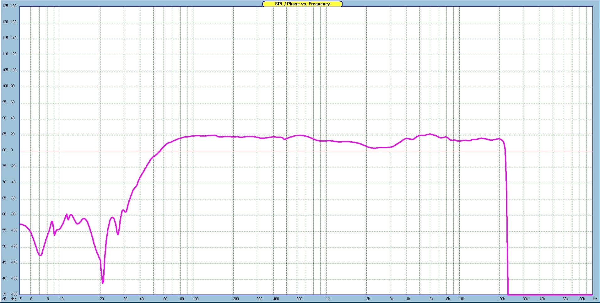
The frequency response is quite impressive for how simple the crossover network is.
The expensive version
Here is the schematic for the complex version of the crossover :

The only difference is the extra ladder delay network. Also, the values of the components have changed. Remember that the tweeter is wired in reverse polarity. Here is the components list for one crossover board (I used Jantzen audio for coils and ClarityCap for capacitors) :
- 3.0 mH Inductor (2 pcs) – (Sound Imports) (Parts Express)
- 0.82 mH Inductor (6 pcs) – (Sound Imports) (Parts Express)
- 5.6 uF capacitor (6 pcs) – (Sound Imports) (Parts Express)
- 4.7 Ohm 10 watt resistor (2 pcs) – (Sound Imports) (Parts Express)

As you can see the response is almost completely flat. There is a small dip at 3.5 kHz, which is -3 dB below linear.

To check the phase relation between the 2 drivers, reverse the polarity of the tweeter and check for a deep null. As a result, the 2 drivers cancel each other nicely at around 2 kHz, which indicates the crossover frequency.
Crossover build and placement
You can actually check the How to build a crossover article and get some tips on how to build one. I made it specially for this project. However, I didn’t like how that crossover end up and I scrapped it and made a new one. I used a birch plywood board which was thinner (I think it was 10 mm thick). The dimensions were 15 x 13 cm. The original board was 15 x 15 and with the piece I cut, to reduce the size, I made 4 little feet.

I didn’t use a null bar anymore to free up some space. As a result, the components aren’t as bunched up as before.

I used 0.5 m long cables, with appropriate crimp terminals for the tweeter and the mid-bass. Use shorter cables for the connection to the binding posts.
As for the placement, I opted for the back panel. This is quite a popular choice. You could use the bottom panel also. I used some wood glue to fix the crossover board to the back panel and leave it over night for the glue to dry. The crossover is pretty heavy and the weight of it will press nicely, to make sure the glue will stick.

As you can see, the crossover fits perfectly into the available space. Make sure you connect the input terminals to the binding posts. You can do this before, or after you place the crossover. Whichever is easier for you.
Inudctor placement is not the most fortunate, but placing 4 inductors on a small board has its compromises. Here is a chart with how to place them for low interference. However, the overall result is good, and that’s what’s important in the end.
Port assembly
The port fits quite snugly into the 4″ hole and doesn’t need any help to remain there. If you force it inside, it will stay there, fixed. However, if you play music, you will hear audible distortion, if you place your ear near the port. This is because the port is not actually fixed appropriately.

Take the port and remove the inner flare.

Apply silicone in excess. Probably works with less, but this is how I like to do it.
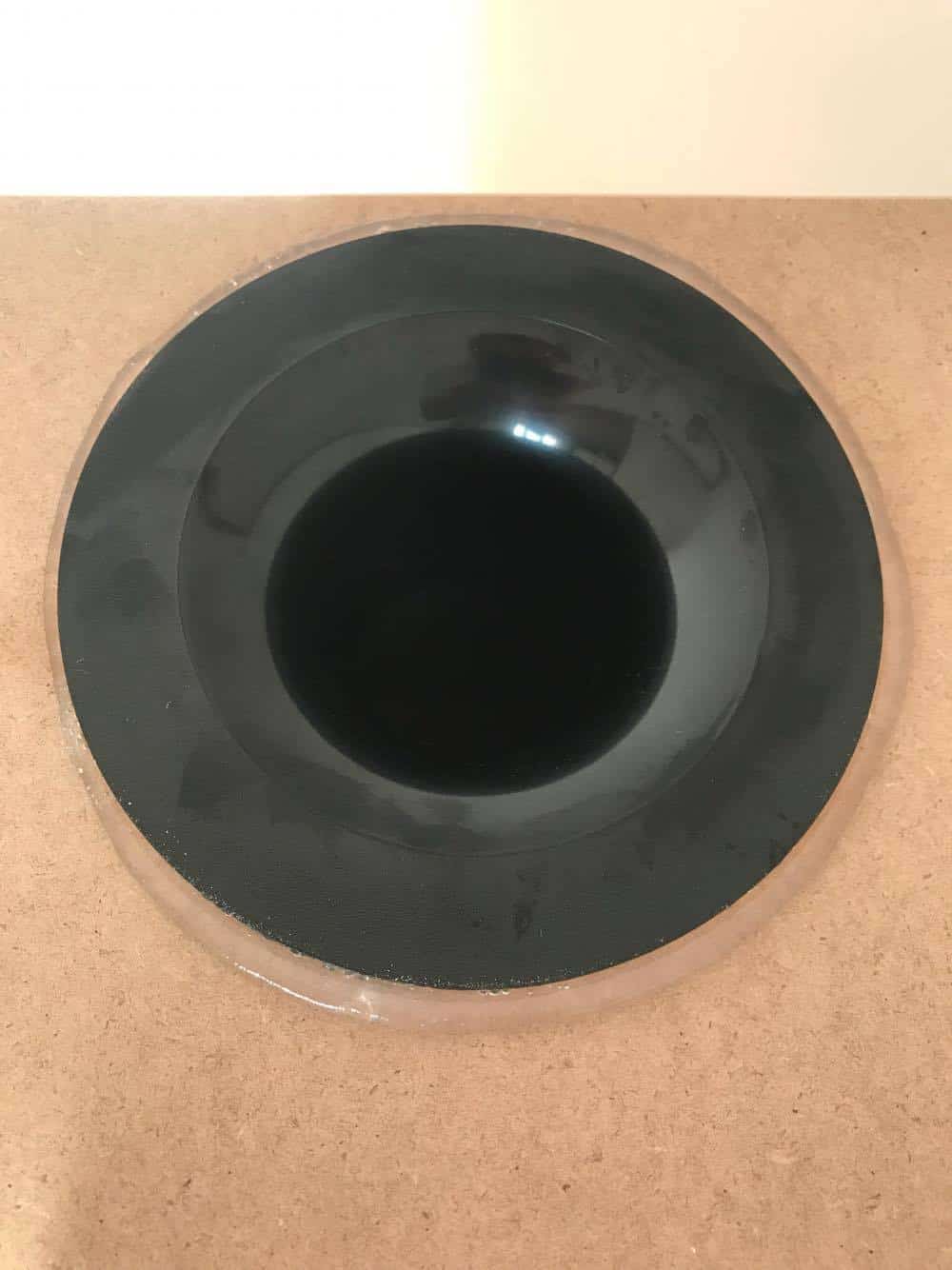
Press the port inside until the silicone oozes out. Let the silicone cure for at least half of day. You can remove the excess after the silicone dries up. After all this, don’t forget to insert the inner flare of the port. Use the mid-bass cutout to access the port from the inside.
Finished enclosure
Here are a couple of pics with the front and back of the enclosure :

Front.

And back.
As you can see, I didn’t apply a finish to it yet. I don’t even know if I’m going to do that. I’m not really good at this part, but some of you are real artisans in this area. Wanted to give them a random paint, but I was too eager to give them a listen. If you are not applying veneer to the box, my advice is to use boards that show the grain of the wood (not MDF), which looks much better.
Conclusion and subjective opinion
This loudspeaker uses components that are not cheap, but not expensive either. Some like to use really cheap speakers when DIY-ing, but I think it doesn’t justify the work put into the project. They are cheap for a reason. Also I gave an option for a cheaper crossover if you want to keep the costs down.
As for the sound signature :
- Very good bass response for a bookshelf speaker.
- Clean and detailed at low and moderate levels.
- Can reach high levels of volume if you want to. The mid-bass seems to be the first to crack down under the pressure (especially if the music has tones under 40 Hz).
- At high volumes they become fatiguing and you cannot listen for long. However, at moderate levels they are a pleasure to listen to and you can go on indefinitely.
- Pretty picky about positioning. On axis listening for best results.
Now that you got yourself some DIY speaker plans, you can start your own loudspeaker project. It sounds awesome for the money, and you will appreciate them even more, knowing that you are the one that built them.
References
- Inductor positioning source : link.
You May also Like


Learn loudspeaker design from scratch

25 comments
Great article, I’m doing something similar with the Seas 5.5″ paper /reed driver, but a Fountek Neo x 2 ribbon tweeter. Crossover design is way beyond me, that is something that I will have to source out, any suggestions in this regard as to who is good to approach? Thanks again.
I dunno, someone local perhaps. As you have to send them the enclosure and the drivers for measurements. Without them you can’t design the crossover properly. Might as well just follow the basic crossover equations but with unpredictable results.
Thanks for the detailed write-up, I am a beginner just beginning to learn about loudspeaker design. Can you please share what software you are using for your frequency modeling?
I’m using SoundEasy, but there are other software options out there for free, like Xsim (for crossover design).
One more silly question.. What type and amount of fill would you suggest for a build like this? Thanks for your expertise!
My recommendation is to use none at all. If it were a sealed enclosure, I would suggest to fill it up with something like polyfill. But since it’s a bass reflex enclosure, don’t use dampening material unless you have panel resonances. This issue doesn’t usually happen in a bookshelf enclosure, especially in a one that is adequately braced. However, you might run into problems with floorstanding speakers. If you do, line the bottom and top walls. If you still have problems, line the sides as well. Try to keep clear of the walls where you have placed the speakers or port and the wall opposed to that (usually the front and back panel).
Do you have a wattage RMS and total sensitivity for the speaker?
Not really, haven’t tested for that.
i have a woofer speaker 18 “1800 watts Qts 0.768 fs 51.14 hz Vas 124.86 how to calculate. to make the speaker box.
If you want to learn how to design enclosures I have a course about this :
https://www.udemy.com/acoustics-101-speaker-design-basics-and-enclosure-design/?couponCode=AJDISC101
If you want a quick answer, just let me know what kind of box you need.
Wa +886955122679
I am interested in building this as a first project. However, the Seas mid bass speaker is no longer available. Can you suggest a drop in replacement?
Unfortunately, there is no drop in replacement.
Seas bass unit is widely available. This looks to be a well though out project.
You can read many articles out there on baffle step, diffraction etc. Troels Gravesen’s articles regarding crossovers are very informative. They explain much of what you shouldn’t be doing such as substituting drive units, changing baffle dimensions or using generic crossover plans.
Thank you so much for this informative build plans, your efforts in detailing what you did is much appreciative. You have spent many hours logging your work and that time is given to us free to enjoy. Thank you.
Dear mr. Tanasescu, hallo Marius,
Thank you for this design, it looks well thought out. I am building a pair. I choose the simple crossover filter, because I am a big fan of very simple filters, I value their spaciousness in sound reproduction higher than a little less than perfect frequency curve. I also think they are an easier load for my tube amplifier.
I have two questions now: -1) Does the tweeter also have to be connected reversed polarity, the same way as you describe for the more complex filter? -2) When finished, do I position the tweeters inside or outside? I think inside, I shall find out, but what are the deeper thoughts behind it?
Hope you find time to answer the questions.
Regards,
1) No, just for the cheaper one, you reverse the polarity of the tweeter.
2) You can place it on either side. Just remember to mirror the 2 speakers. If the left and right speakers have the tweeter on the same side, it will look awkward, because there is no symmetry. Not placing the tweeter in the center helps with diffraction.
Marius, are you sure the answer on question 1 is right? I don`t understand the answer. reverse. You say I dont need to reverse, and in the second half of the answer you say reverse it. I read in your article that for the more complex filter you need to reverse polarity. That is perfectly clear to me, but for the simple filter it is not.
Do I miss something?
Regards,
Yeah, I got it the other way around. The complex one needs reverse polarity on the tweeter. For the simple one, the polarity is normal.
Thanks for the swift answer
Hey Marius, what software are you using for your cutting template?? I have all my dimensions but just want a cutting template, cant find it online
That’s subwoofer design toolbox.
How much phase cancellation between drivers at the crossover point when polarity is reversed is “enough.” Do we have a -dB target to hit or is there an objective way to measure this to have extremely good phase response?
There is no golden number. But I would say at least -20 dB.
Would you consider doing a video/article on phase perfect/transient perfect speakers and crossover orders/types that aim to achieve this? How they look on axis and off-axis? This seems to be the most confusing part of designing a high quality speaker with superior imaging. Or is phase just overhyped and not really that important as it appears?