
Passive crossovers for speakers – made easy
Poor man’s passive crossover
The passive crossovers for speakers are the most complicated component when in comes to loudspeaker design. This is depending on how much you want to complicate things and how perfectionist are you. To make a high quality passive crossover, you need to have measuring tools, to measure impedance, frequency response and phase response. Also, you need a crossover design software, to calculate and optimize your response curves. Otherwise, by using trial and error, it could take ages before you obtain a decent response. In this article, I will cover the exact opposite : How to make a passive crossover with no measuring tools and no design software.
Methodology
How are we going to achieve this goal, without any equipment? Simple, you have to assume that there will be some sort of compromise. While it will not be the best crossover design, it will give a decent separation and, most important, it will provide protection to the tweeter so you don’t burn your speakers. When making passive crossovers for speakers, in the absence of measuring equipment, you will have to rely only on the spec sheet of the speakers.
Since we are talking about budget crossovers, we will focus only on 2 types :
- 1st order Butterworth.
- 2nd order Linkwitz-Riley.
For the second order crossover, we will add some additional components into the design, to see if we get better results :
- Impedance equalization circuit.
- Shunting resistor.
- Notch filter.
We already know that the impedance of the speaker varies with frequency, so getting the impedance graph to look more like a flat line will ensure better results.
Devices under test
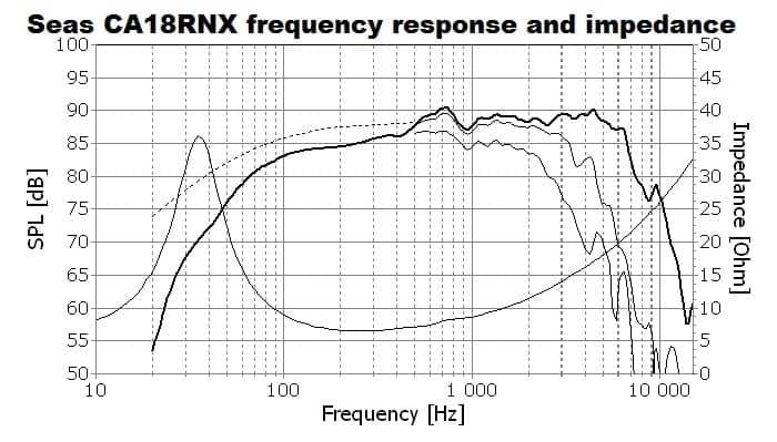
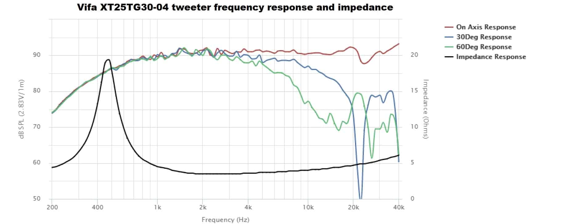
I will take each crossover design and measure the frequency response. After that, we can compare them and draw a conclusion. To generate the response curves, I’m going to use a Seas CA18RNX (Amazon affiliate paid link) mid-bass driver in a bass reflex enclosure tuned at 52 Hz, and a Vifa XT25TG30-04 (Amazon affiliate paid link) tweeter.
Considering we don’t have any measuring equipment, we have to rely solely on the parameters provided by the manufacturer. Also, the frequency response chart and the impedance chart found in the technical sheet of the speaker is of great aid.
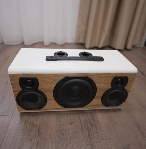
Just to give you a visual perspective on how the speaker box actually looks, here are some pictures with the front and with the back.
 I attached all the parameters and charts above. for convenience’s sake.
Passive crossovers for speakers recap
If you are not familiar with passive crossovers for speakers, I suggest you go ahead and read on how they work and take a look at the circuit schematics for each type. Like I said earlier, we are going to focus on a 1st order Butterworth filter, and a 2nd order Linkwitz-Riley. To put all information in one pot, here is, once again, the schematics and the component formulas for each of the 2 crossover types. If you don’t understand what the letters stand for, make sure you read the articles linked previously.
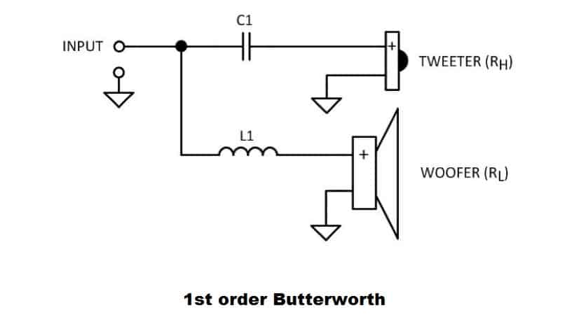
To calculate the values of the capacitor and inductor use these formulas :
- C1 = 1 / (2π * fC * RH) .
- L1 = RL / (2π * fC) .

To calculate the values of the components, use these formulas :
- C1 = 1 / (4π * fC * RH) .
- C2 = 1 / (4π * fC * RL) .
- L1 = RL / (π * fC) .
- L2 = RH / (π * fC) .
Now you are probably thinking that this is easy from now on. Simply set a crossover frequency and calculate the values for each component. Discouragement incoming! First of all, these formulas assume that the speaker acts like a resistor (with a fixed impedance value). But that is not the case. Impedance varies with frequency. On the other hand, you have to take into consideration speaker placement, baffle size, acoustic centers of speakers, phase etc. If you want to design a high end crossover, you have to take a lot of variables into account. Happily, this is not the purpose of this article. The goal is to make passive crossovers for speakers which are simple and good enough.
First step
Normally, you would have to choose a crossover point, but before we do that, let’s look at the efficiency of the drivers. In most cases, the tweeter is louder than the mid-bass driver and needs attenuation. Since we don’t have any measuring equipment, we need to rely on the specification sheet. We are looking for the efficiency at 1 watt / 1 meter. If it’s quoted at 2.83 V we need to transform it.
How to design loudspeakers - video courses


Let me give you a quick example on how to transform 2.83 V into 1 watt / 1 meter. Let’s say a driver is quoted at 90 dB @ 2.83 V. Then, we need to look at the impedance :
- If the driver is 8 ohms, then the efficiency is 90 dB @ 1 watt / 1 meter (the same).
- If the driver is 4 ohms, then the efficiency is 87 dB @ 1 watt / 1 meter (3 dB less).
- For drivers with impedance of 2 ohms, the efficiency is 84 dB @ 1 watt / 1 meter (another 3 dB less).
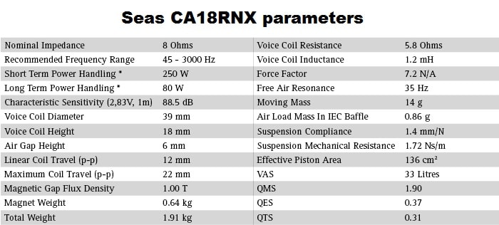
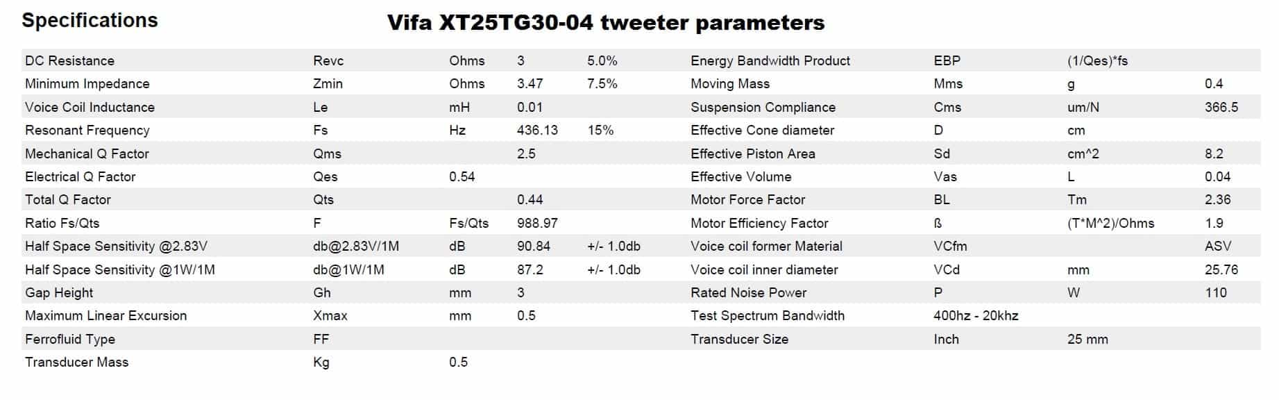
So, for the mid-bass driver we have 88.5 dB at 2.83 V. But since the driver is 8 ohms, it has the same efficiency value (88.5 dB) at 1 W/1 m. The tweeter has the efficiency quoted for both types, and the one we are interested in is 87.2 dB at 1 W/1 m. So in this case, the tweeter has a lower output compared to the mid-bass. Since it’s only 1 dB difference, we can consider them having roughly the same output. In case the tweeter is louder than the mid-bass, you need to put a resistor in series with the tweeter to tame it down.
Actual measurement of the speakers
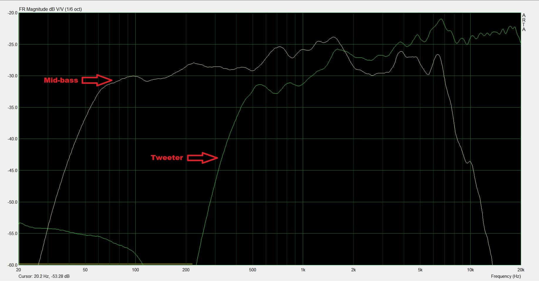
When we actually measure them, we can see that the tweeter is actually louder by a couple of decibels. This can happen for several reasons. First of all, you have to take the parameters quoted by the manufacturer with a grain of salt. It even says +/- 1 dB on the tweeter spec sheet. Secondly, you have to take into account the acoustic centers of the speakers, which is considered to be in the place of the voice coil. While both speakers are mounted flush on the baffle, the acoustic center of the mid-bass is around the magnet area, which is behind the tweeter. Therefore, the tweeter is actually in front (acoustically), compared to the mid-bass. Since it’s in front, it will be a tad louder.
Judging from the graph, there shouldn’t be any reason to tinker with the efficiency. So, we made a correct assumption just by judging the spec sheet. Anyway, you can always listen to the finished speaker, and subjectively tell if the tweeter is too harsh. If so, adding a resistor in series with the tweeter will tame it down.
You can see a dip in the response between 2 kHz and 4 kHz, for both the mid-bass and the tweeter. This is actually some baffle step issue. You can fix it in the crossover design. Also, you can off-set the tweeter. Placing it closer to the side of the baffle (not in the center), will mitigate this problem. However, we are not aware of this issue as this article assumes we have no measuring tools. As I said in the beginning, compromises will be made, and we shall continue.
1st order Butterworth filter
Now when you are building some passive crossovers for speakers, and decide you want to use a 1st order filter, you are already making a compromise. These filters don’t provide adequate protection for the tweeter. There are some speakers which are designed with 1st order filters in mind. However, even those have some issues at certain frequencies (particularly the resonant frequency of the driver). In conclusion, you choose a 1st order filter because you want it to be cheap, because you are lazy, because you’re installing the filter in a car and you don’t have where to put the other components, etc.
Many times, when this solution is selected, a single capacitor is used for the tweeter and nothing else for the mid-bass. Mainly for protection, so the tweeter doesn’t burn out. However, we are going to test a complete filter, with a high pass filter for the tweeter and a low pass filter for the mid-bass.
Calculation
So let’s start to calculate the values for the components. Being a 1st order filter, I suggest a crossover frequency of at least 6 kHz. Let’s go for this number, as any higher than that will be pointless for the mid-bass, as it starts to reach its natural roll-off. The impedance for the tweeter is 4 ohms (RH = 4) , the impedance of the mid-bass is 8 ohms (RL = 8), and the crossover frequency is 6 kHz (fC = 6000).
- C1 = 1 / (2π * fC * RH) = 1 / (6.28 * 6000 * 4) = 6.64 μF
- L1 = RL / (2π * fC) = 8 / (6.28 * 6000) = 0.21 mH
The closest components I have is 6.8 μF and 0.22 mH.
So, the circuit diagram should look like this :
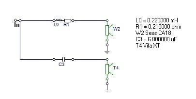
R1 is actually the resistance of the inductor (not a separate resistor). You can tell that from the icon in the circuit diagram. After hooking all the components up, here is the frequency response :
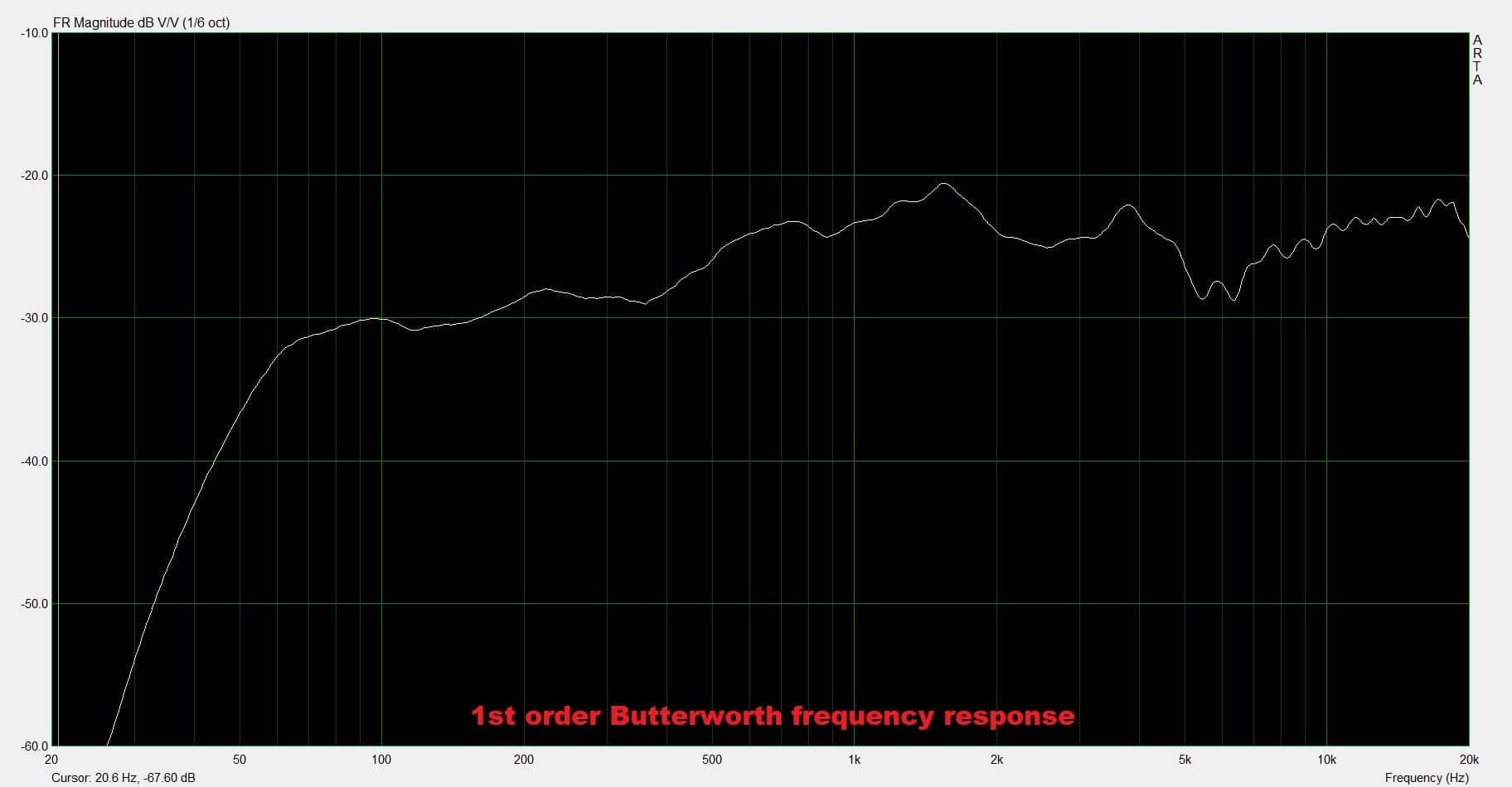
The frequency variation is about 8 dB, which is pretty bad, but forgivable for a crossover which was made blindfolded. The problem here is that protection for the tweeter is not good. If you have some music rich in frequencies close to tweeter Fs, and you turn the volume up, you might permanently damage the tweeter.
2nd order Linkwitz-Riley
When you are designing passive crossovers for speakers, choosing a 2nd order Linkwitz-Riley (or LR2 for short) is a great pick. It provides adequate protection for the tweeter, the responses sum up flat and it has only 4 components. Lesser components means less complications in the audio signal path, and of course, cheaper filter.
First of all, we need to choose the crossover frequency. Unlike the 1st order filter, we can go lower in frequency. The resonant frequency of the tweeter is around 450 Hz. Which is insane. Don’t even think about going close to that. It’s a tweeter after all. If we look at the response curve, it’s starts to roll off at 1 kHz. Go at least 1 octave above that, so 2 kHz. But just to be safe, I picked the crossover frequency at 2500 Hz.
Now to calculate the components :
- C1 = 1 / (4π * fC * RH) = 1 / (12.56 * 2500 * 4) = 7.96 μF (closest cap I have is 7.8 μF).
- C2 = 1 / (4π * fC * RL) = 1 / (12.56 * 2500 * 8) = 4 μF (closest cap I have is 3.9 μF).
- L1 = RL / (π * fC) = 8 / (3.14 * 2500) = 1.02 mH (closest inductor I have is 1 mH).
- L2 = RH / (π * fC) = 4 / (3.14 * 2500) = 0.51 mH (closest inductor I have is 0.51 mH).
Here is the circuit diagram :
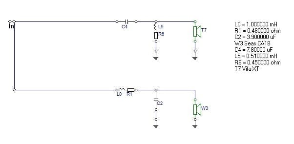
After setting up this filter, here is the frequency response :
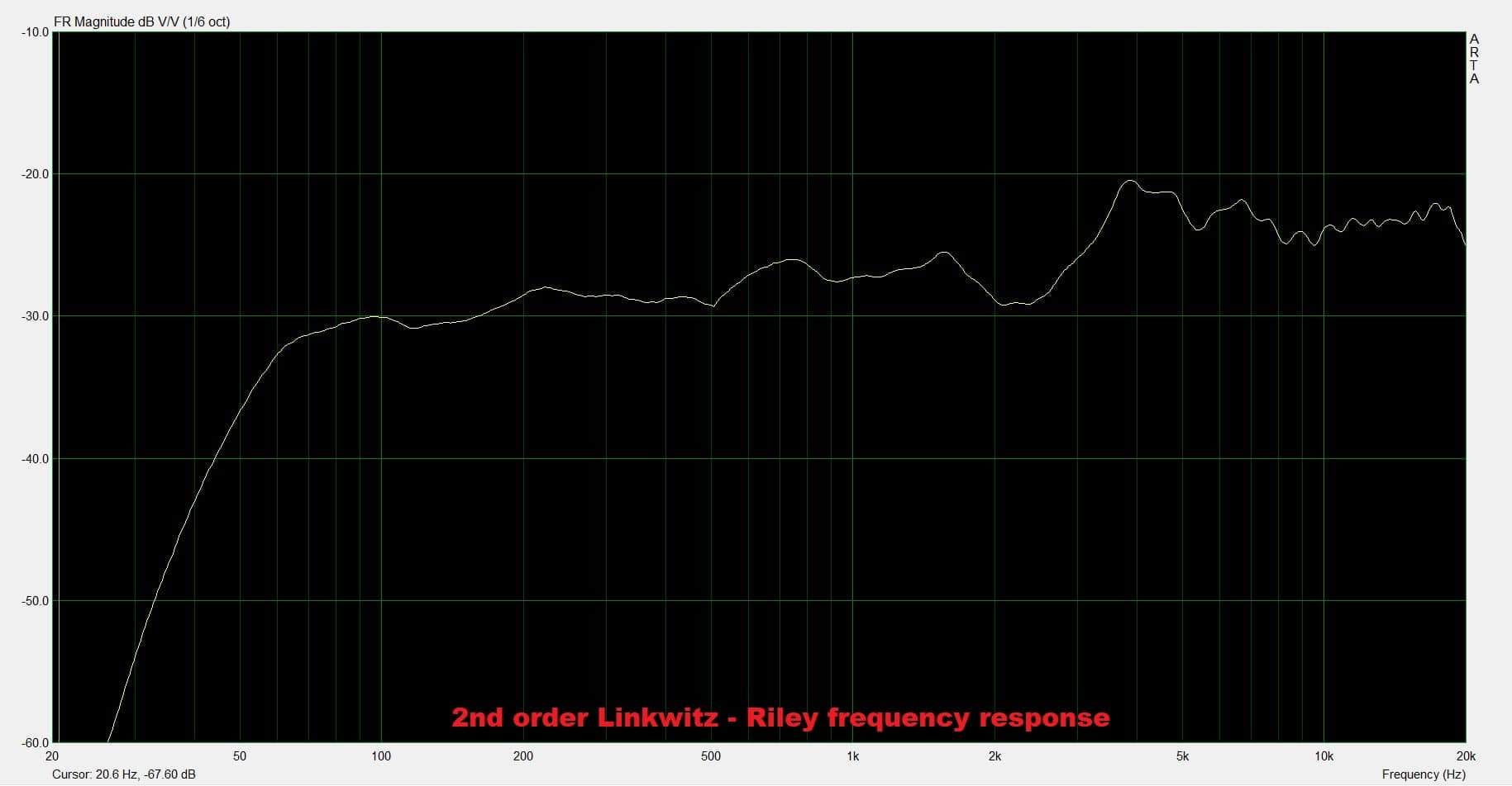
We can observe that the mid-bass response is much more linear now. However, the tweeter is significantly louder.
Revised LR2
Now you have to trust your ears (since we presumed that no measuring tools are used) to tell you if the tweeter is louder. In this case, the tweeter dominance is quite noticeable. Therefore, a series resistor is in order. You can play with different resistor values and listen to how it sounds. I’m going to go with something around 3 ohms, same as the tweeter’s Re. In a perfect world it would double the resistance of the tweeter and halve the input power, so the SPL would go down by -3 dB. I will use a 3.3 ohm resistor.
Here is the circuit diagram with the extra resistor :
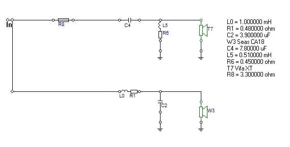
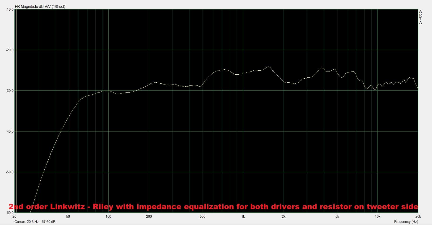
And, again, here is how the frequency response looks like :
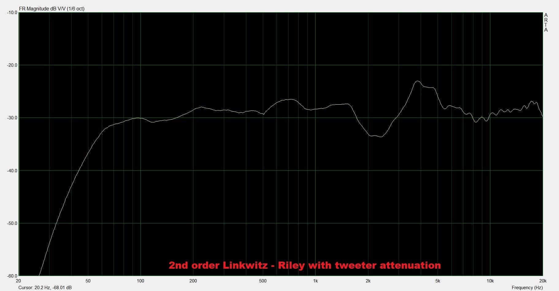
The response is much more linear, except for the dip at 2.5 kHz. That dip is actually the baffle step effect of both tweeter and mid-bass stacking together, creating that dip. Placing the tweeter offset to the side will reduce this issue. Again, we have no way to tell. However, the response is pretty decent. Excluding the dip at 2.5 kHz and the peak close to 4 kHz, it looks quite linear.
Flattening the impedance curve
We know that when you measure the impedance of a speaker in free-air, you will have a spike at the resonance frequency, and after that, the impedance will progressively go up as frequency increases. To make the impedance have a more steady value across the frequency range, we will use 2 tricks : a Zobel network for the mid-bass driver, and a notch filter for the tweeter.
Mid-bass
Fortunately, there is a separate article I made about the Zobel network, and I suggest you check it out. The same speaker was used so there is no point in doing this again. In conclusion, the values for the components are as follows:
- Resistor = 6.8 Ohms.
- Capacitor = 22 μF.
Since the impedance is now flattened (for the high frequencies at least, where the filter will take effect), we will not use the nominal impedance (8 Ohms) to calculate the crossover components. Instead, using the DC resistance (Re = 5.8 Ohms) would be more appropriate. So let’s recalculate the components for the mid-bass section :
- C2 = 1 / (4π * fC * RL) = 1 / (12.56 * 2500 * 5.8) = 5.5 μF (closest cap I have is 5.6 μF).
- L1 = RL / (π * fC) = 5.8 / (3.14 * 2500) = 0.74 mH (closest inductor I have is 0.74 mH).
Tweeter
The tweeter has a big spike at resonance frequency, and we need to flatten that out. Again, there is a separate article concerning the notch filter, which uses this exact same speaker. The values for the components of the notch filter are as follows :
- Capacitor : 100 μF.
- Inductor : 1 mH.
- Resistor : 4.6 Ohms.
Once again, since we flattened the impedance curve of the tweeter, we are going to recalculate the values of the components from the tweeter section. This time we are going to use the DC resistance values instead (Re = 3 Ohms) :
- C1 = 1 / (4π * fC * RH) = 1 / (12.56 * 2500 * 3) = 10.62 μF (closest cap I have is 10.47 μF).
- L2 = RH / (π * fC) = 3 / (3.14 * 2500) = 0.38 mH (closest inductor I have is 0.39 mH).
Having said all that, let’s unite all of it into a circuit diagram :
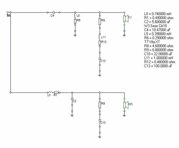
Now let’s look at the frequency response :

We can definitely hear that the tweeter is a tad louder, so let’s implement some tweeter attenuation.
Tweeter attenuation
Again we are going to add a 3.3 Ohm series resistor for the tweeter :
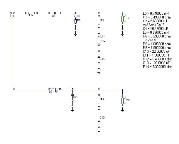
Now let’s take a peek at the frequency response :
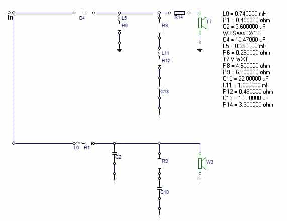
The response looks a bit more linear now. However, let’s try to move the resistor close to the tweeter, see how that affects the frequency response. So, here is the diagram again :
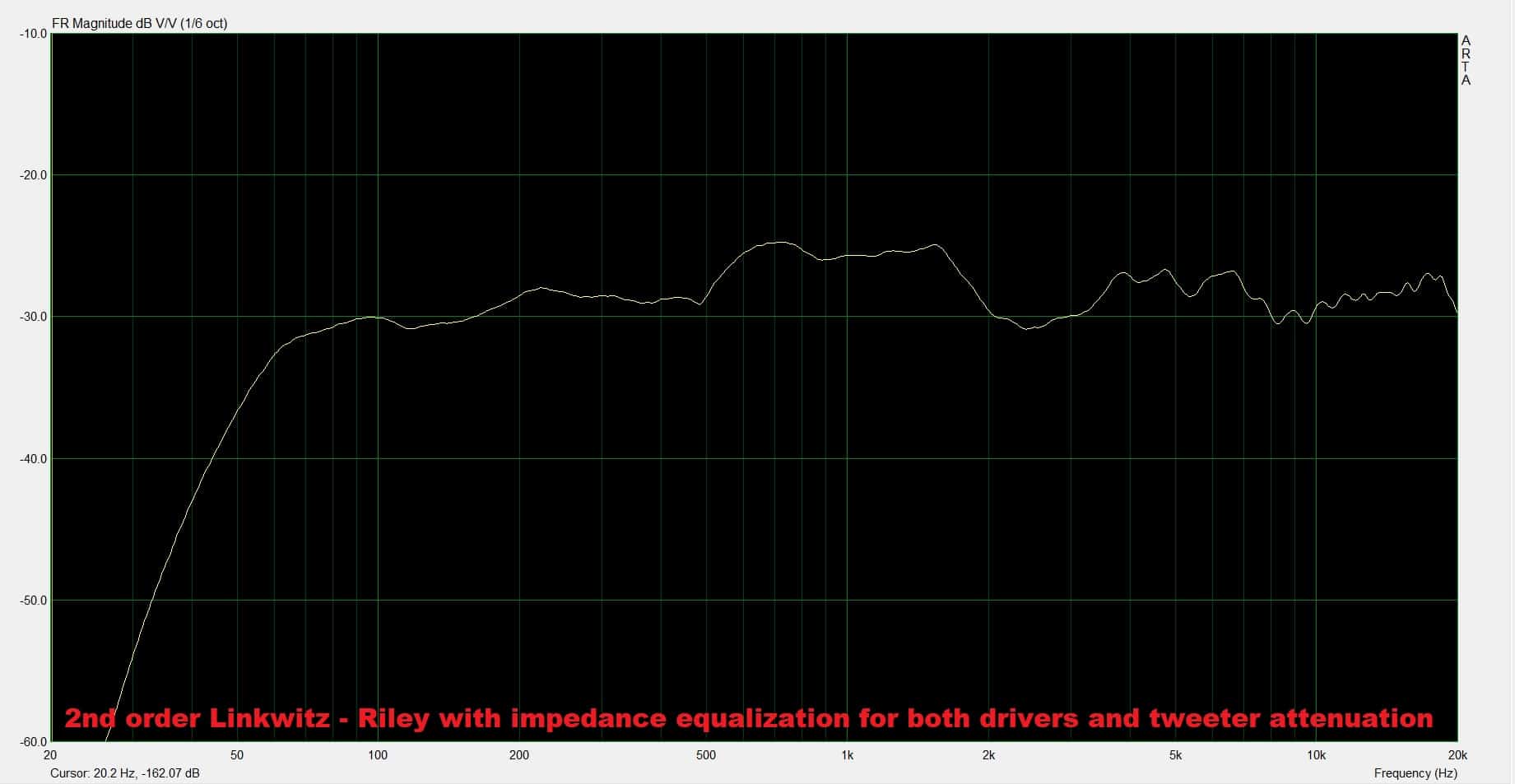
And finally, let’s look at the frequency response :
The dip in the response at 2.5 kHz is not as pronounced now. You can definitely play with the position of the resistor and see how it sounds.
Conclusion and subjective opinion
Making passive crossovers for speakers is really an art. A difficult one, I might add. I don’t really see the purpose of making one without measuring tools. At least having the ability to measure the frequency response is definitely a plus. Looking at the last frequency response, you might be contempt with the result. However, let me give you the facts. The bass frequency response (sub 100 Hz) is poor compared to the midrange, which is significantly higher in amplitude (somewhere around +6 dB). The bass response is not bad, by itself. If you push the volume up, you will get good bass response. But if you do that, the mid-range is so loud, that you need to turn it down.
So, you see, linearity is very important. Having a variance of more than 3 dB across the frequency range is a problem which cannot be ignored. You could use these speakers with a subwoofer. It would be a great combo. Or you can get yourself some measuring tools and a crossover modeling software and start building crossovers with minimal flaws.
References
- Loudspeaker Design Cookbook 7th Edition by Vance Dickason (Audio Amateur Pubns, 2005).
- Introduction to Loudspeaker Design: Second Edition by John L. Murphy (True Audio, 2014).
- Image source : AI generated


Learn loudspeaker design from scratch

14 comments
Hi Marius,
Were the speakers mounted in a built box when you doing the measurement and tweaking the crossover? Or were these measurements taken where the speakers just mounted on a baffle?
I was wondering if you would design and build the enclosure, then start working on the crossover? or the other way around?
You have to finish the enclosure and then do the measurements. Compared to a simple baffle, the enclosure changes the impedance curve, it alters the low end response, introduces diffraction effects and alters phase response (especially on speakers with slanted or asymmetrical baffle). So, yeah, you have to measure the speakers placed into your exact enclosure. After that, you can start working on your crossover.
Thanks for the advise!
I have an 8 ohm speaker cabinet and would like to build a circuit that will place an additional 8 ohm load and make the cabinet perform at 4 ohms. Thank you
That will achieve nothing. You can place an 8 ohm resistor in parallel with the speaker and create an overall 4 ohm load, but you will decrease the efficiency of the driver. My advice is to leave the 8 Ohm driver alone and use it like that. You won’t stress the amplifier as much and the efficiency rating will remain unchanged.
Gosh !! I am a pharmacist and no physics knowledge but a DIY diehard. I want to build a floor standing but no knowledge of this network circuitry. :-(. I think for me is to buy a built one from a company.
That will protect your drivers from burning out, the tweeter is mean (considering you match the impedance). But it will not make for a perfect blend between the drivers. I guess it will be good enough though, but the result is unpredictable (you could have phase issues and cancellations on some frequencies).
Thank you very much for the informative articles.
If I may ask, a 3 way crossover too please. I am trying to finish a long time project of 3 way floor standing speaker, the good ‘ol Vivace from Elektor with the Vifa drivers.
Regards,
Ioannis
Well, the whole point of this article is to tell you that you are working blind without measurement gear. The fact that things kinda worked out in this scenario, was a fortunate event. You can’t really get a crossover right using some formulas, especially for 3 way. I have made a course about crossover design. If you want to learn more you can check it out in the course page.
Thanks for helping me understand how this stuff works! I am converting an old tower sub / satellite system into a “portable” bluetooth system. I think all of the drivers can be re-used except for the satellite tweeters. In trying to understand how the system is designed, I’m trying to reverse engineer the lower crossover. It looks like a first order crossover — There is only one inductor, in series with the woofer and a capacitor in series with the midrange driver. However, there is another capacitor in parallel with the woofer terminals. The woofer and midrange drivers are nominally 8 ohm and the lower crossover is 120Hz. The value I calculate for the lower crossover capacitance is 165 uF and the capacitor installed in 150 uF. I can’t tell what the inductor value is — the calculated value is 10.6 mH. The ‘extra’ capacitor, across the woofer terminals is 200 uF. Can you tell me what the expected impact of this cap is? I haven’t started on the upper crossover. It is supposed to have a crossover frequency of 3000 hz. The satellites, which house the mid-range and two tweeters appear to have a 2nd order crossover, with two inductors but 3 capacitors (and some LPad resistors, I think). I think it has something to do with the impedance mismatch between the mid-range and the tweeters. All 3 drivers have a DC resistance of about 6.5 Ohm, but the tweeters are in parallel, so the effective DC resistance is ~3.2 Ohm. I don’t have the crossover out of the satellite enclosure yet, so I can’t tell how things are wired up. In the end, I plan on re-using the woofer and mid-range drivers, so I’ll probably leave the lower cross-over as-is. I want to replace the two tweeters with a single tweeter and I’ll later want to understand how to best approach that.
Designing crossovers is much more complicated. As I shown in this article, without measuring equipment you can’t really tell what you are doing. And by using crossover calculators you will go nowhere. You will protect the drivers (especially tweeters from excessive bass), but don’t expect linear frequency response, unless you are lucky. You can check out my course page if you want to learn more about crossovers. If not, you can simply reuse the old crossover. And from what I understand from you, on the tweeter branch, there are two 8 Ohm tweeters. Just get a decent one with 4 ohm impedance (presuming those 2 are wired in parallel).
The L-pad you mention is to reduce the output of the tweeters. 2 tweeters will surely be too loud compared to one mid-range.
Thanks very much for your reply. I do plan to re-use the existing woofer, midrange, and lower crossover. The higher crossover is now out of the satellite and it looks like a 2nd order two way crossover except that there is a 5 W, 1.8 Ohm resistor in series with the tweeter and upstream of the tweeter capacitor and a 5W 6.5 Ohm resistor downstream of the capacitor that is in parallel with the midrange. In the end, I do plan to find a 4 Ohm tweeter to replace the two 8 Ohm tweeters and see how the system sounds with the existing crossovers. My main interest was making sure I didn’t blow anything up and get decent (decent to me, anyway, I’m not an audiophile, by any means). I will go to your course page to get a better understanding, even if I don’t have a real means to assess my system when I’m done (other than my ears!)
Please take note that you do need some equipment if you want to take the courses about crossover design. To make crossovers you need a measurement microphone and a device to measure impedance. I posted a DIY solution on how to measure impedance and TS parameters using your sound card on youtube. But the microphone you will have to buy.
Can an Audyssey setup mic be used like the one i have from my AV reciever