
Speaker equivalent circuit / electrical model
What is an analogous speaker circuit?
The speaker equivalent circuit is the actual core of the theories crafted by Thiele and Small. Every component of a speaker can be “transformed” into an electrical component, to form a circuit that acts exactly the same as the speaker (electrically). Let me put it another way. You can measure the impedance of a speaker. Now imagine that you get different resistors, inductors and capacitors, and arrange them in such a way, that when you measure the impedance of this newly formed circuit, it’s exactly the same as the impedance of the speaker. A similar thing happens when you place the speaker in a box. Additional components are added to the circuit. That is how Thiele and Small manage to predict the behavior of enclosures.
Brief description about speakers
Before we get to the speaker equivalent circuit, we need to understand how a speaker works in the first place. Let’s start with some proper terminology. The technical term for speaker is transducer. This is because it transforms electrical energy into acoustical energy. But this happens in two phases. Firstly, the electrical signal (received from the amplifier) is converted into mechanical movement, by setting the voice coil into motion. Secondly, the cone is starting to move along with the coil and creates differences in air pressure. By doing so, the mechanical movement is converted into acoustical output. When we will start to model the electrical circuit, these changes from electrical to mechanical and mechanical to acoustic, will appear as transformers.
Simplified speaker equivalent circuit
Let’s start with a simplified version of the electrical equivalent circuit and then we will build up, with more details, so it will be more clear. Before we get into this, I suggest you read a few articles related to this, so I don’t catch you off guard with some alien terminology. Go ahead and read this, this and this.

As you can see above, this is the most rudimentary electrical representation of a speaker. Normally you would have a inductor in series with the Re resistor, to simulate the inductance of the voice coil, but we leave it out to simplify things. So you will just have the resistance of the voice coil (Re), wired in series with an inductor, resistor and capacitor (which are wired in parallel between them), which simulate the motion impedance of the speaker. This speaker equivalent circuit will make a curve, that will look like an impedance chart of a speaker.
Let’s define the terms :
- Re – The DC resistance of the voice coil. In the impedance chart, this will correspond to the point of minimum impedance. When you are looking at the chart, there will be a spike at resonance frequency. Then the impedance will go down and then start to rise up again, due to voice coil inductance. At the point where it starts to rise, the phase angle is 0 degrees, and the impedance is at its minimum (that is Re).
- fs – The resonance frequency.
- Ts – Related time constant. Ts = 1 / ωs = 1 / 2πfs .
- QM – Mechanical quality factor. This is the ratio of the parallel resistive component of the motional impedance (RM) to its reactance at resonance.
- QM = RM / XM.
- XM represent the combined reactance of LM and CM from the circuit.
- QE – Electrical quality factor. This is the ratio of the series DC resistance (Re) to its reactance at resonance.
- QE = Re / XM.
- QT – Total quality factor. This is derived from the electrical and mechanical quality factors and they add up like resistances in parallel.
- 1/QT = 1/QE + 1/QM.
This is the simplified version. Now let’s go more into detail and see what’s really happening.
The electro-mechanical process
In the first part of the transformation process, the speaker will turn the electrical signal into mechanical movement. This means that the speaker is a transformer, which further means that the speaker is an impedance converter. The speaker will have a certain electrical impedance input and a certain mechanical impedance output. The ratio of the transformer directly influences the output impedance.
How to design loudspeakers - video courses


How do we transform all these mechanical elements into electrical ones? Well, fortunately, mechanical and electrical units are interchangeable without the use of constants. This means that a given power (in Watts) can result from the product of a current and a voltage, or the product of a force and a velocity. For this reason, every mechanical part of the speaker has an electrical equivalent and can be modeled electrically into a speaker equivalent circuit.
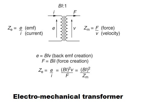
So as you can see above, an electrical impedance (e/i or voltage/current) is converted into a mechanical impedance (Force/velocity). Now let’s introduce this new element into our speaker equivalent circuit.
The transformer in our circuit has a ratio of Bl:1. The B*l product is the factor that determines the output mechanical impedance. The force of the voice coil (in Newtons) is given by the product of the flux density in the gap, B (in Tesla), the length of the coil wire actually in the gap, l (in meters), and the current measured in amperes. The back-emf (volts) is the product of B (Tesla), l (meters) and the velocity (meters per second).
This means that the analogy is as follows :
- Velocity analog to voltage.
- Force analog to current.
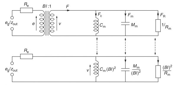
Lastly, we can remove the transformer from the picture and create an equivalent circuit.
The mechano-acoustic process
Say hello to the 2nd transformer, which converts mechanical impedance into acoustical impedance.
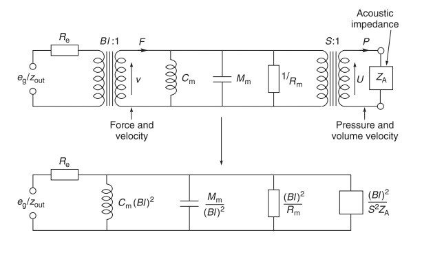
The ratio of this 2nd transformer is given by the surface area of the diaphragm (S). So, the first time we transformed current and voltage into force and velocity. Now, we are transforming force and velocity into pressure and volume velocity. After we remove the transformers from the picture we get the equivalent circuit from below.
Final speaker equivalent circuit
After all of these transformations, let’s reveal the final analogous electrical circuit. To complete the circuit, the inductance of the voice coil has been added in series with Re.
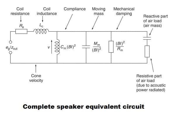
This is the complete electrical equivalent circuit. The formulas for calculating each component look different from the ones stated in our first, simplified example. But this is only because it uses different variables, the results will be the same.
Speaker in a closed box
What happens when you place a speaker in closed box? Evidently, the circuit will change. The variable introduced by the closed box is its compliance. As a result, the compliance of the box will show up on the circuit diagram as an additional inductor.
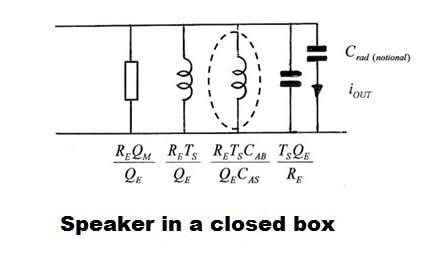
What is interesting is that it acts exactly like a 2nd order high pass filter. If you remember from the passive crossover article, the difference between a 1st order and a 2nd order high pass filter is that you add an inductor in parallel. The roll-off slope of a sealed enclosure is 12 db / octave because of this reason.
Explanation of new terms :
- CAB – Compliance of the box.
- CAS – Compliance of the speaker.
Conclusion
Getting to know the fundamentals of a speaker equivalent circuit, can really push your understanding on how a speaker works and how will it perform in a given enclosure. Furthermore, if you get comfortable with how the values of these electrical components are affected, you can judge a speaker by just a glimpse at its T/S parameters. So, if you want to build a certain type of enclosure, you know what to look for.
References
- Loudspeaker and Headphone Handbook 3rd Edition by John Borwick (Focal Press, 2001). (Amazon affiliate paid link)
- AES 124th Convention : Loudspeaker Parameters (Master Class) – By Neville Thiele and Richard Small.
- Image souce : link.


Learn loudspeaker design from scratch

8 comments
Thank you! A very clear explanation.
The mechano-acoustic process has an S:1 transformer, but it should be 1:S (you can also see that S^2 goes in the denominator, whereas BL^2 goes in the nominator). Also, your input is a current of eg/Zout, but you should just put a voltage of eg, since that is what is always applied anyway. And I guess that the block with Za, should really be 1/Za, since the independent variable p acts as the dependent variable current.
Hi!
I’ve checked the simplified equivalent circuit on SB Acoustics TW29BN-8 tweeter and calculation gives an impedances that are aproximatelly -0,5 dB lower than those from the impedance chart and that is great.
When comparing MW16P-8 woofer’s chart with calculation, it gives about 17% lower impedances then chart, which is due to the resistive and reactive part of air load not calculated. How does it can be known from the TS parameters of the woofer? Or coupled with the enclousure..
I’ve calculated from 2kHz to 2,6kHz.
Thanks!
Not -0,5 dB, but -0,5%
I’ve found the formulae for air load impedance. Still it’s not accurate with that MW16P-8 woofer (in datasheet Le=0,2mH – same as 4 ohm version) and that is suspicious. When calculate with Le=0,4mH, result is at 1% same as on the graph, on 2kHz.
Checked on SEAS W22EX001-E0022, diference from graph is about 4,50% at 2kHz.
“So you will just have the resistance of the voice coil (Re). wired in parallel with an inductor, resistor and capacitor, which simulate the motion impedance of the speaker.”
You mean ‘series’ since you are talking about Re. The inductor, resistor and capacitor are wired in parallel with each other, but the resulting group is in series with Re.
Great article, btw., otherwise I wouldn’t have bothered to comment.
Well spotted! Fixed.
What is written about “Speaker in a closed box” is incorrect. Speaker parameters Lm, Rm, Cm are parameters at acoustic short circuit when acoustic impedance Za is zero and acoustic circuit is open. When you put the speaker in a closed box, there is no more acoustic short circuit, but acoustic radiation apears due to acoustic load with reactive and resistive part, so you add compliance of the air in the box, but you also add some air moving mass and air resistive load. It is also not clear at what condition of speaker Thiele-Small parameters are measured – free speaker in air at acoustic short circuit with measured parameters Lm, Rm, Cm of speaker, or in closed box or other with measured parameters of speaker plus some acoustic load, which makes using these parameters questionable.