
Baffle step calculator – with circuit examples
How to compensate for diffraction gain?
To simplify things, you can use a baffle step calculator, devise a simple circuit, and reduce the boost in higher frequencies caused by the baffle diffraction. If you are not familiar with the diffraction effect, make sure you check out this article : Speaker baffle design and diffraction.
Baffle diffraction is quite predictable, if you have adequate software to help you model the response, like SoundEasy. In this article we shall see :
- What are the main factors which influence baffle diffraction.
- How does the response look like in various cases.
- Calculate a simple circuit to fix the issue.
- How does altering the circuit components, affect the overall response.
Device under test
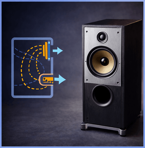
For our little experiment over here, we are going to use a 2-way bookshelf speaker, with the following drivers :
- Vifa XT25TG30-04 – tweeter. (Amazon affiliate paid link)
- SEAS CA 18 RNX – mid-bass. (Amazon affiliate paid link)
And here are the exact dimensions of the baffle :

When we will conduct the measurements, the crossover will be bypassed, and we shall ignore the tweeter also. We are interested in the pure mid-bass response, without any filtering.
Why? Because the tweeter has all the frequencies boosted by the baffle (since it plays the top end of the frequency band). If it’s too loud, a simple series resistor will suffice. As for the mid-bass driver, we shall see where the response starts to go down a bit (diffraction loss), as the baffle gets too small compared to the wavelength of those frequencies. The so called step, baffle step. In what’s about to follow, we will use a simple baffle step calculator, to correct this issue and flatten the response.
Modeled baffle response
When people talk about baffle gain, they tend to simplify things. Which is fine, I’m not against that. However, let’s try to put things into perspective. Baffle diffraction is not as simple as : starting from this frequency upward, the response will get a +6 dB in output. From “said” point downward, the boost gets progressively lower until the baffle has no effect at all.
This is the simple version. In reality, baffle response is affected by many factors, and can go up and down as frequency increases. In conclusion, the baffle response will never be as smooth as described earlier, unless multiple conditions are satisfied.
Here are some of the factors that shape baffle response :
- Shape of the enclosure (sphere, cylinder, rectangle etc).
- Size of baffle.
- Location of the speaker on the baffle.
- Location of the listener / microphone.
- The shape of the edges (if the enclosure is boxy).
- Is the enclosure wrapped in absorbent material?
Let’s give an example on our specific enclosure :

You can see how the response starts to rise, as we go up in frequency. Also, there are some irregularities in the response. These are ripples mostly caused by edge diffraction.

Here is the same enclosure but with the edges rounded and the speaker placed to the side of the baffle (not in the center). As a result, the response is more smooth, with less ripples.
Baffle step calculator
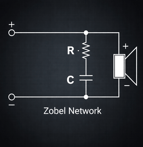
To flatten the response we are going to compile a simple circuit, which will go in series with the speaker.

The circuit is rather basic and it contains only one inductor and one resistor. To put it into common terms : the inductor decides the frequency point from which the attenuation starts, and the resistor the amount of attenuation.
The main factor that decides which frequencies get an amplitude boost is the width of the baffle. This is considering the baffle is rectangular, and the length is noticeably larger than the width. You shouldn’t stress much on this criteria, as it is almost always the case.
How to design loudspeakers - video courses


R2 is equal to the nominal impedance of the driver. In our case 8 ohms. so R2 = 8 ohms.
L1 is equal to the width of the baffle (in centimeters) times the value of the resistor divided by 102. So if we look at the baffle schematic, we can see that the width is 22.7 cm. So L1 = 22.7 * 8 / 102 = 1.78 mH.
This baffle step calculator looks simple enough, but let’s see the result. They usually need tweaking.
Results and tweaking
First of all, let’s take a look at the response of the raw driver (inside the enclosure, of course).

The graph shows the impedance, phase and frequency response, so it looks a bit cluttered. Try to focus on the bold red line, which is the frequency response. It is evident that the response start to rise beginning with 500 Hz, as a result of baffle diffraction. Let’s see what happens when, the compensation circuit is in place.

The amplitude of the frequencies in question are lower. This might be satisfactory, but could be better. It’s easy to tell in this case, because there are measurements available. If not, you could tell by listening, if the sound is bright / harsh. If that is the case, increase the value of the resistor.

The result of this is taming the higher frequencies even further, just by increasing the value of the resistor from 8 ohms to 12 ohms. For the sake of this exercise, I’m going to increase the value of the resistor once again, and check the results.
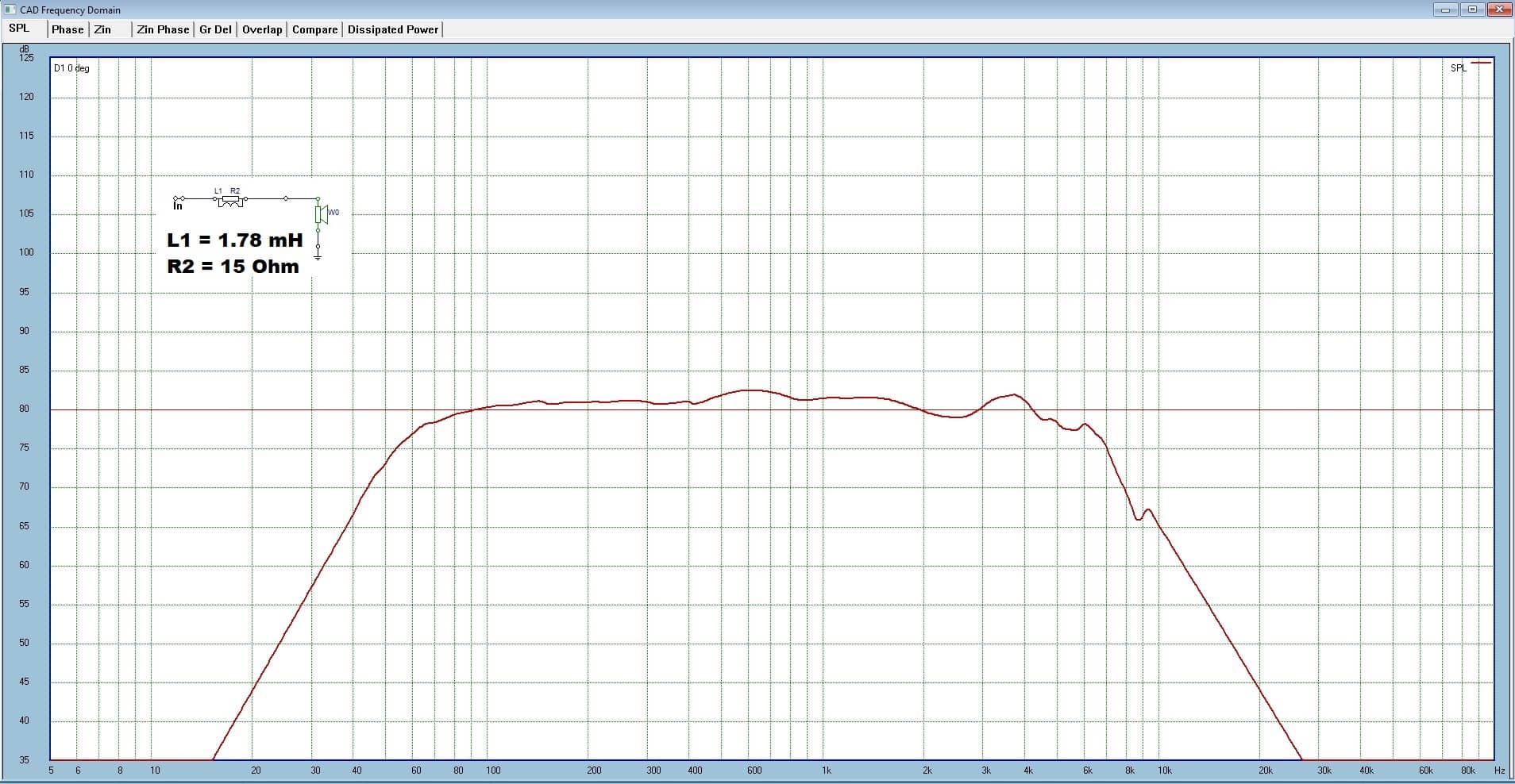
Looks quite decent. Trial and error, listening tests and patience will get you good results.
Conclusion
These aren’t set in stone formulas to get precise results. This is because speaker impedance varies with frequency. You either have specialized software that takes this into account, or you use this simple baffle step calculator and adjust accordingly, to get to the results you are after.
References
- Loudspeaker Design Cookbook 7th Edition by Vance Dickason (Audio Amateur Pubns, 2005).
- Master Handbook of Acoustics by F. Alton Everest, Ken Pohlmann (McGraw Hill Professional, 2009).
- Image source : AI generated
You May also Like


Learn loudspeaker design from scratch
