
Zobel network calculator – Impedance equalization circuit – Step by step
Flattening the impedance curve
A zobel network or an impedance equalization circuit is always a good idea when it comes to passive x-overs. Because impedance changes its value depending on frequency, it creates certain problems. Impedance will have a bump at resonance, and then it will slowly rise (as frequency increases), due to voice coil inductance.
Here is the thought process of why you should consider an impedance equalization circuit :
- The values of the components of the crossover network are dependent on the impedance of the speaker.
- If the impedance changes, so does the crossover frequency.
- In conclusion, if the impedance remains constant, the crossover frequency will keep its value, regardless of frequency.
Quick example :
To make a 1st order low pass filter for a mid-bass driver, all you need to do is to add an inductor in series with the speaker (more info here).

The value of the inductor is calculated using this formula (for a Butterworth design):
L1 = Z / (2π * fC).
- L1 = inductance of the inductor (in Henries).
- Z = rated impedance of the speaker (in ohms).
- fC = crossover frequency (in hertz).
Let’s say the speaker is 8 ohm and we want to cross it at 2000 Hz.
L1 = 8 / (2 * 3.1416 * 2000) = 0.63 mH.
So, if we add a 0.63 mH inductor in series with the speaker, we will attenuate all the upper frequencies by 6 dB / octave, starting with 2 kHz. This remains true, if the impedance value remains constant, which we know it doesn’t.
Impedance vs frequency
Let’s use a real world speaker and make an impedance equalization circuit (also known as Zobel circuit / network) for it. The speaker I chose is SEAS Prestige CA 18 RNX (Amazon affiliate paid link). A 7″ mid-woofer, which will serve as an example on how to flatten the impedance curve.

The nominal impedance of this driver is 8 ohms. As you can see from the graph, the impedance rises steadily with frequency. As a result, this will interfere with the way the crossover network will work. To fix this, all we need to do is to check the zobel network calculator and implement the circuit.
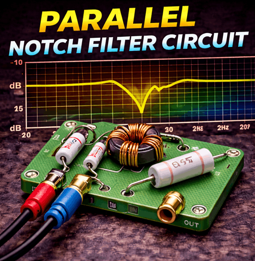
Impedance equalization circuit / Zobel network calculator
We all get intimidated by electrical circuits, don’t we? However, there is nothing to get concerned about, when it comes to a Zobel circuit. All you need is a resistor and a capacitor. That’s it!
Electrical diagram :

To calculate the values of the electrical components, you just need some speaker parameters:
- R = 1.25 * Re
- C = Le / R2
- Re is the DC resistance of the speaker.
- Le is the inductance of the voice coil of the speaker.
- R and C are the values of the resistor and capacitor for the impedance equalization circuit.
How to design loudspeakers - video courses


Let’s use these formulas for our SEAS CA 18 RNX speaker. You can find the spec sheet here. Anyway, we are extracting only the parameters we need : the DC resistance and the inductance (Re = 5.8 Ohms and Le = 1.2 mH). After that, we can calculate the values of the resistor and capacitor :
- R = 1.25 * 5.8 = 7.25 Ohms
- C = 0.0012 / 7.252 = 0.000022 = 22 μF
Flattened impedance
Now that we know the values of our components we can assemble the circuit. Sadly, I could only manage a 6.8 Ohm resistor, but it’s close enough.

After setting up the impedance equalization circuit, I did another impedance sweep, to see what the Zobel network has done to the impedance curve.

Finally, the impedance has flattened, and it’s nice and smooth. You are probably wondering: What about the hump at resonance? There is no concern regarding the impedance spike at resonance. This is because we are making a low pass filter for a mid-bass driver. In conclusion, we are filtering the high frequencies, so the hump at 40 Hz doesn’t affect the crossover network. However, if we are talking about a tweeter, that’s a different story. When making a high pass filter for a tweeter, the spike at resonance is something to worry about. Anyway, we will talk about how to flatten tweeter’s impedance on a different occasion.
Conclusion
The Zobel network / circuit is a good choice when it comes to designing passive crossover networks. Some people disregard it, as it can require a rather large capacitor, which are quite expensive. Nevertheless, it’s very easy to design and implement. The hard part is when you start to tinker with the actual crossover network.
References
- Loudspeaker Design Cookbook 7th Edition by Vance Dickason (Audio Amateur Pubns, 2005).
- Electrical Networks by A. Henderson (Arnold, 2014).
- Image source : AI generated
Learn loudspeaker design from scratch

11 comments
I have recently started a web site, the information you offer on this site
has helped me greatly. Thanks for all of your time & work.
It really helped me a lot to be more professional. Thanks to you . I am from Bangalore
An article on phase would be interesting.
I think many would like a better understanding of how acoustical phase relationship between mids and tweeters affect the summed frequency response.
And on how electrical phase can affect the performance of amps. I’m told electrical phase is a very important factor when using some tube amps.
Does the resistor in the Zobel network affect the resistance of the driver (Re)? Technically, couldn’t two resistors in parallel drop the resistance to levels that might hurt the amp?
Asking for a 4Ω speaker.
Thanks.
Zobel network is a cap and resistor in parallel. And yes, if the value of the resistor is low enough you can shift the impedance below the driver Re (only for the higher frequencies though, because of the presence of the capacitor). But by doing that, the zobel network is implemented incorrectly and defeats the whole purpose of smoothing out the impedance response.
That means….
1) Zobel network is significant to woofer.
2)Tweeters don’t need it or rather you didn’t take the topic here.
My query is what watts of resistor should we use.
Lastly thanks a ton for a really wonderful explanation.
You can use it for tweeters as well. But you are more concerned about the spike in impedance at resonant frequency which is around the 1khz mark (for tweeters), because that is where the crossover will be active (filters bass frequencies not high frequencies.
To get an accurate way of telling how many watts it needs you should use XSim and make the circuit there. Add a component power dissipation chart, and check all of the components, including the resistor. If you don’t know what I’m talking about you can check the passive crossover network course : https://www.udemy.com/course/loudspeaker-engineering-how-to-design-speaker-crossovers/?referralCode=6D5FACD391A4CBBF4135
If we purchase a readymade crossover and calculate the Zobel network with their given crossover frequency, will it solve the issue of designing the cabinet according to the resonant frequency?( for those who don’t know how to measure all the stuff and specs of speakers and those who don’t have the setup and software for doing all this things)
Not really. If you buy a ready made passive crossover, just use it as it is. It will protect the drivers from burning out, but don’t expect good frequency summation between the two. It could be, but most likely it isn’t.
I have always wondered why the resistor value is 25% higher than Re. Could you elaborate?
What about when you only have R_e(DC resistence of coil) but don’t have Le?