
DIY Isobaric speaker design – with examples
What happens when you put two speakers in isobaric?
Let’s dive into the DIY isobaric speaker design and see what happens. We are going to build some speaker boxes and measure them up and see what’s up. Basically we are going to test the theory. First of all, if you prefer watching instead of reading, you can check out this video over here :
If not, you can stick around and keep reading this article.
What’s the isobaric theory
Well, basically, you have 2 speakers which are identical. You place these speakers either cone to magnet, or cone to cone, also called clam shell. In the clam shell design you have to wire one speaker in reverse polarity so that the speakers move into the same direction. If you want more information about the theory of isobaric compound loading, you can check out this article.
How to design loudspeakers - video courses


Anyway, let me give you the short version. When you place 2 speakers in isobaric, the pocket of air between the speakers binds them together. Since only one speaker cone emits sound (the other is tucked away inside the box), you can imagine that the 2 speaker combine into one speaker with different characteristics.
Parameters that change
You will be surprised to hear that most of the parameters remain unchanged. Well, at least the important ones. So we have to add the moving mass of both speaker. Therefore, the moving mass is doubled. The suspension characteristics of both speakers needs to be added as well. In conclusion, “this speaker” is twice as rigid, therefore compliance is halved. Since Mms is doubled and Cms is halved, Fs will remain the same. So here is the short version of what happens to the T/S parameters in a DIY isobaric speaker design :
- Fs (resonant frequency) stays the same
- Qts (quality factor) stays the same
- Vas (equivalent compliance) is halved
For this reason, if you have 2 speakers in isobaric, you can make a box twice as small, with the same result as if you would have only one speaker in full size box. In addition, if you wire the speakers in parallel and your amp can handle half the loud of one speaker, in theory, you will get the same amount of power.
DIY speaker design build
What are we building? Well, first of all, I have 2 Scanspeak 26W/8534G00. I’m going to make 4 different boxes:
- 50 liter sealed box with 1 speaker
- 25 liter isobaric cone-to-cone (clam shell)
- 25 liter isobaric magnet to cone – small as possible chamber protruding outside the baffle
- Same magnet to cone but with the isobaric chamber same size as the baffle
In theory, these enclosures should match in terms of frequency response and resonant frequency.
Build log
Here are some pictures with the enclosures :

So this is the 50 liter sealed box with only one speaker. This will be the reference enclosure. All the other boxes should measure exactly like this one.

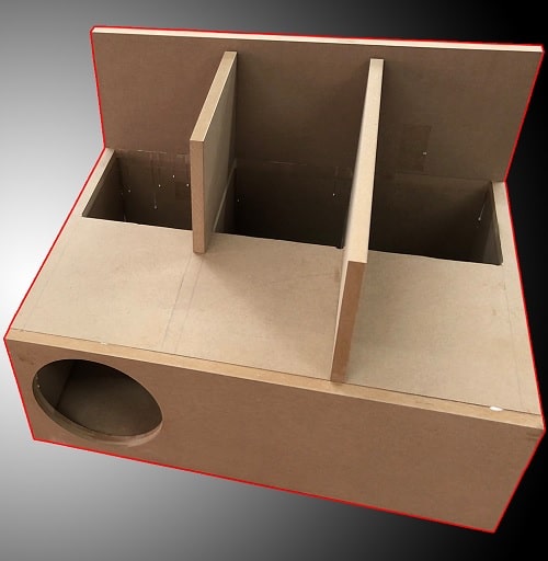
This is the push pull design. To mount the second speaker I used an additional panel. In this case I can remove the speaker with no hassle. Otherwise the inside speaker is kinda trapped inside the box.

This is the DIY isobaric speaker design with the indenting chamber. Keeping the volume to a minimum. However, it looks pretty awkward.

This is exactly as the enclosure beforehand. The only difference is that the isobaric chamber is extended to be the same size as the baffle.
Results
Let’s check the results :

You want to focus on the red curve. That is the frequency response of the sealed 50 liter box. The rest of the curves should overlap that one. We can see that they pretty much overlap. Except for the clam shell design. I don’t really know why that is. The explanation I came up with is that it’s a measurement error. Since the magnet is sticking out. I cannot get a good nearfield measurement. Can’t place the microphone as close as possible to the middle of the speaker cone.
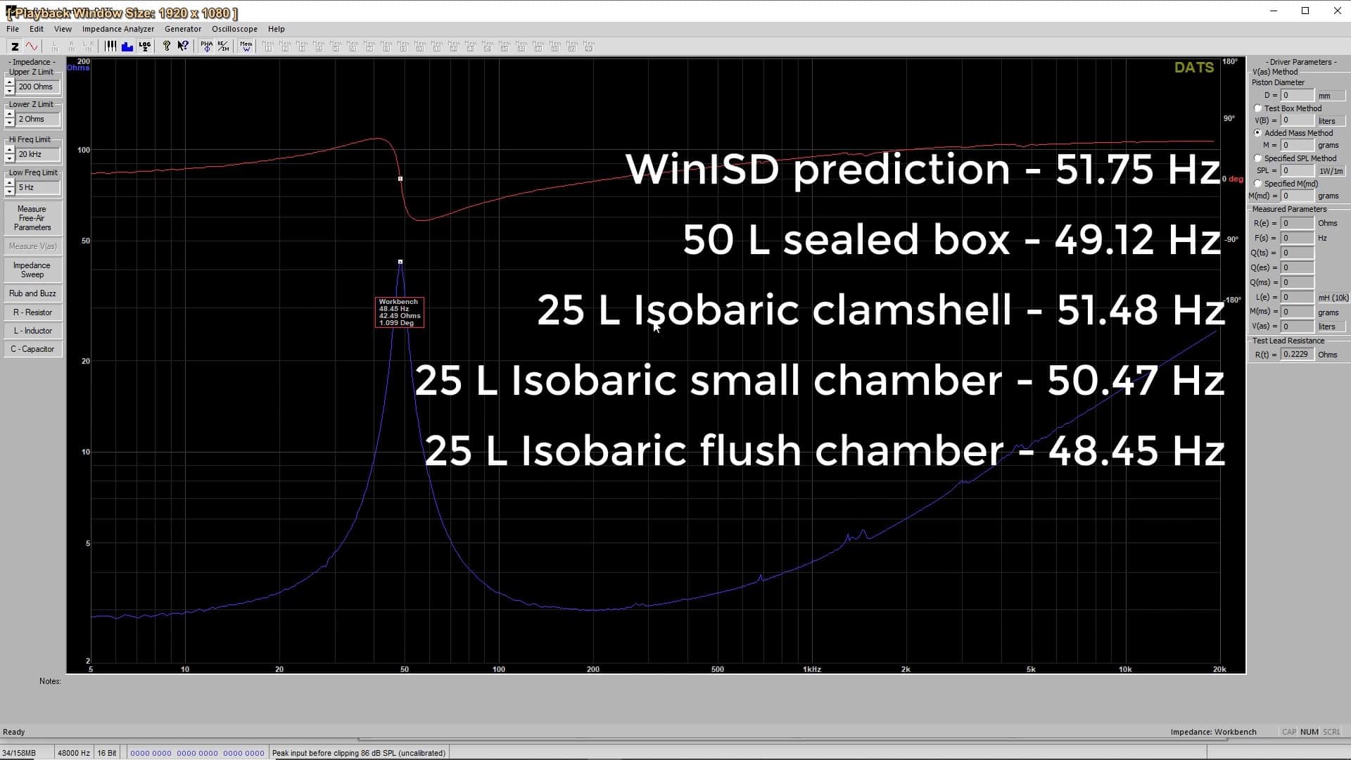
If we look at the impedance results. I won’t post all the pictures, just the numbers. So the results are pretty much 1-2 Hz off. Which is within margin of error, I guess. It’s actually interesting that the resonant frequency goes down as the isobaric chamber gets larger and larger. Check out the numbers.
Conclusion
So when you make a DIY isobaric speaker design, you really must care about enclosure size. To be honest, I don’t think it’s worth the extra speaker. You can buy the appropriate speaker in the first place. However, if you plan to build a 4th order or a 6th order bandpass enclosure, this might be handy. Using a clam shell design which is hidden inside the box. And since these boxes can get pretty large, the fact that you make them smaller seems worth it.


Learn loudspeaker design from scratch

6 comments
Good article, greetings from Bulgaria, I just read you are from Romania.
This article reminded me of a car we bought many years ago, it was some old Fiat but it came with a Pioneer subwoofer in it. Being somewhat of an audio enthusiast I took it apart to see what was inside it because no speakers were outside the box and this was weird to me. As far as I remember the design 2 speakers with their own closed chambers firing into a third chamber with 2 ports. I was like … WTF is that?!?! I guess it was an isobaric bandpass ?! I knew it was some clever dark magic but it did work nice and it was very compact as well. Interesting stuff.
Unless I misunderstood, that’s not an Isobaric Bandbass, just a bandpass… as both drivers are contributing in positive summation.
In Isobaric, there’s only one driver propagating into the room, … the motors are combined, yet there’s still the swept volume of a single driver radiating into the cabin or room.
Typical;
Two motors driving two cones
Isobaric;
Two motors driving a single cone
America has not been discovered. Although it’s nice to see the measurements that confirm the theory – there are very few of these on the web. I’ve looked all over the internet about isobric information, a lot of theory but no practical measurements. That’s why this article is so cool. If you could still do distortion measurements it would be perfect.
most informative, thank you, I see you are a well informed and that I have much to learn! was that your speaker course on Udemy? I bought htis last year and still refer.
Yeah, I have several speaker design courses on udemy.
I’ve used the clam shell system in my car for many years. 4x 12″ subs mounted in my spare tire we) in a Mustang GT. There is a great difference in output when 2 driver is disconnected compared to when both are connected. Are your graphs showing drivers connected in parallel or series.
The way amps are made now, with max output achieved at 1 ohm loads, 4x 4 ohm drivers works perfect. Been running this way since 2008. I used 4 identical drivers and I’ve used 4 different drivers that were all similarly designed. I’ve used brands like jl audio, mtx, Xtreme, Kenwood, coustic and even ran 4x 15’s (I didn’t care for the 15s). No real planning was done. Just ran a divider across the short width, cut holes in it and placed a ¼” aluminum plate over the opening. Screwed he plate around the outer edges and into the center divider to keep it from flexing.
Only recently I have moved to 2 x dual voice coil ATGs, I gained a little bit of trunk space, I’m old now and don’t drive much. My interests have moved to house stereos and my next project is to change a pair of Martin Logan Hybrids Electrostatic speakers into an isobaric configuration. They use a single 8″ sub/woofer that plays up to 400Hz. The subharmonics are not there. I’ve tried a bunch of drivers and found little change.
Many times the speaker cabinet shape and volume will dictate the sound that can be made more than the driver can. There’s some high end manufacturers that claim this to be the most important part of their design and will not give details on which shape is optimal and even hide it with a larger outer cabinet that covers the inner chamber. Of course these are speakers costing over $40k and they will not be taken apart or the warranty will be void.
They say the size isn’t as important as the shape and proportions. Of course I can’t help but figure that the old coffin shape has to be something that needs to be investigated.
I have a Mirage BPS150i sub that claims to be an isobaric configuration, but it’s just 2 subs aimed out both sides that share the common chamber. It’s quite nice sounding for 2 x 8 inch drivers. Those same drivers mounted in the Martin Logan cabinets sound nothing like the Mirage cabinet even though they are similar in size. Maybe ⅔ the volume of the Mirage, you’d think they’re retain some of their sound but they sound exactly like the original Martin Logan drivers and even test nearly the same too.
I’ve encountered the same thing with my tests using Klipsch Heresy’s, no matter what 12″ I’ve tried I can’t get the bass any lower than the stock woofers. I’m convinced that the cabinet sets the bass limitations, it has to be due to shape and proportions. If it’s 1x1x1.5 and all sides are parallel, it will only allow a certain lower limit.
The Logans are more of a 1×1.5×2 proportion with all parallel sides, with an 8″ driver yet they both seem to have the same low limit. They test showing they can reach down to 30Hz but it’s not with any authority. My last build used a 10″ and a 12″ in 2 separate cabinets, the 10 was in a 12×12 sealed cube and the 12 was in a larger Heresy sized cabinet but taller, together they hit 24Hz and it was like adding another dimension to the sound, you could feel it as well as hear it. I can’t achieve that now with the single 8″. I’m hoping the additional 8″ aimed out the back wired out of phase will do the trick. The Mirage has both drivers wired in phase, so it’s not an isobaric. The rear woofer will help reinforce the rear sound waves coming from the panel (out of phase) and should add that extra hitting power. It won’t be a true isobaric configuration but it will be operating along with the panels just like it’s 2 separate speakers, one facing at you in phase and the rear will reflect off the rear wall and meet the front in phase.