
Measure Thiele Small parameters using free software
How to measure impedance and T/S parameters using Room EQ Wizard
If you want to measure Thiele Small parameters you need specialized equipment. The most easily accessible one is the DATS v3 ( [Sound Imports] [Amazon] [Parts Express] affiliate paid links) It’s easy to use and affordable(-ish). However, what if you are really stingy and you don’t want to fork out the cash for the Dayton Audio device. Or maybe you just want to do a speaker impedance measurement once in a while, so it doesn’t make sense to buy something like this. In that case, I might have a DIY solution for you. In this article you will find all the parts needed to build the measurement jigs. However, all of the instruction for measurements and stuff are found on the YouTube video.
Parts list
Here are all the parts you will need to make the 2 jigs (Amazon affiliate paid links):
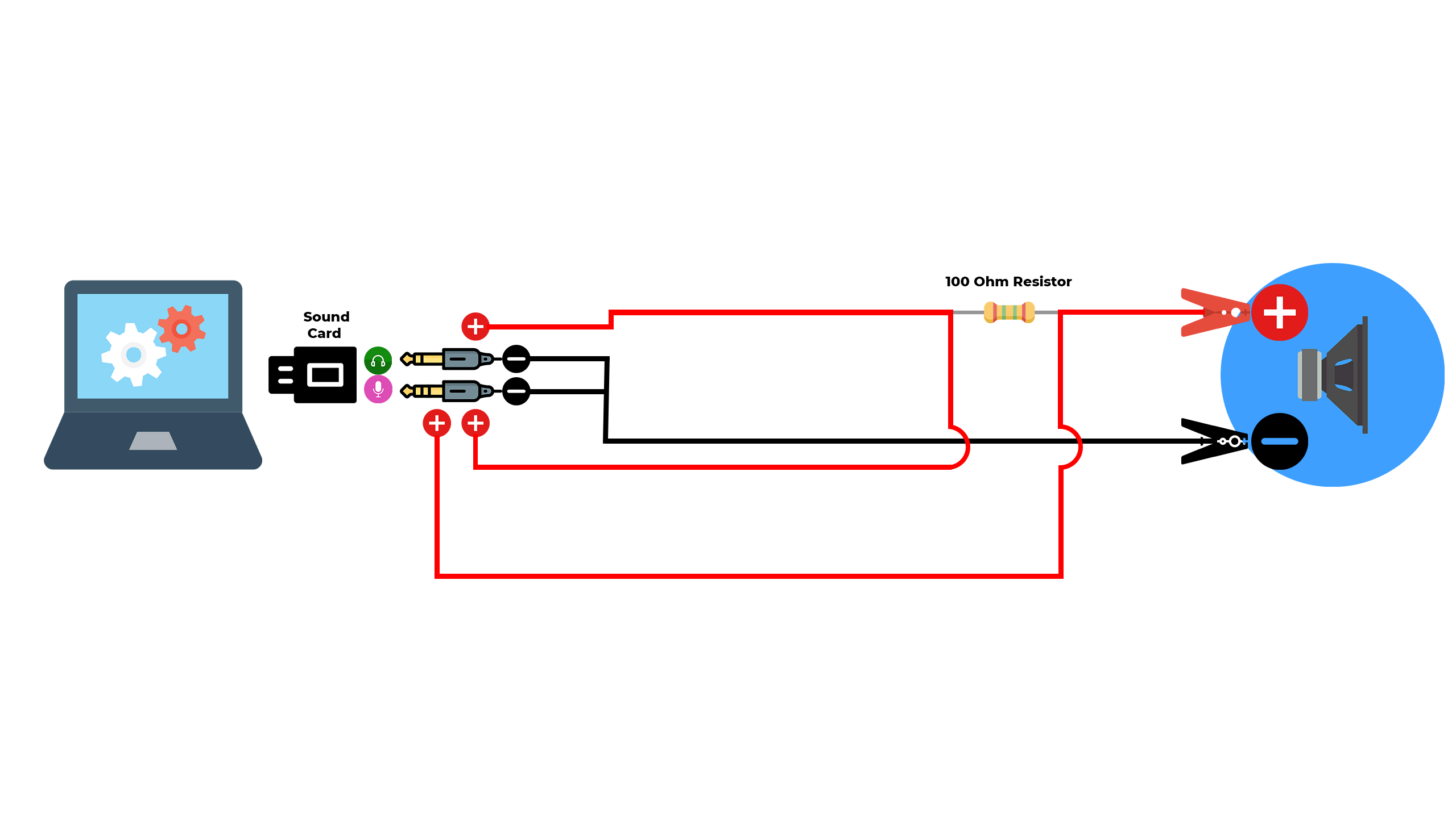
The simple jig for the headphone out:
- Mono Jack
- Stereo Jack
- Cable – 2 x 0.75 mm2 (18AWG)
- Heat shrink tube
- Alligator clip – 1 pair (red-black)
- 100 Ohm resistor – something like 1W should be more than fine
- 33 Ohm resistor
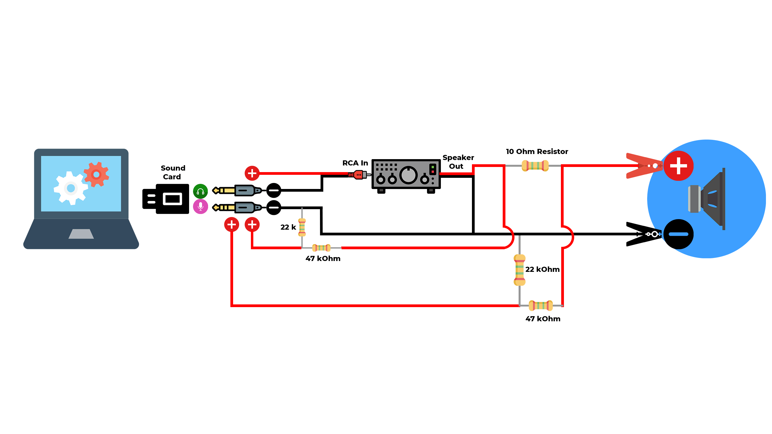
The advanced jig with an amplifier:
- Mono Jack
- RCA plug
- Mono jack to RCA cable (don’t buy the previous 2 items if you get the cable ready-made)
- Stereo Jack
- Cable – 2 x 0.75 mm2 (18AWG)
- Heat shrink tube
- Alligator clip – 1 pair (red-black)
- 10 Ohm resistor – something like 1W should be more than fine
- 33 Ohm resistor
- 47 kOhm resistor(2 pcs) – 0.5W like the one linked is no problem
- 22 kOhm resistor(2 pcs) – 0.5W like the one linked is no problem
I understand that some parts sell in packs of 10, 25, 50 and you only need 1 or 2. Maybe you already have some at home, though I doubt you have 47 kOhm resistors lying around. Anyway, maybe you have some local electronics store where you can buy small amounts.
Sound Card
Besides these parts, you will also need a soldering iron, and of course a computer or laptop with a working sound card. Since we mentioned a laptop, there might be an issue here, because most laptops have combo jacks for their on-board sound card. We need individual connections for the headphone output and the microphone input. Combo jack has a guaranteed mono microphone and we need a sound card which has a stereo mic input. As a result, getting an adapter from one socket to two sockets will not fix things. Furthermore, getting an external USB sound card won’t guarantee that you have a stereo mic. In addition, most manufacturers don’t specify that the mic is mono or stereo, so it’s going to be a challenge to find a good sound card.
- External sound card. You don’t need something fancy. Just something which you can connect to USB, and it will give you 2 connections : for the headphone and for the microphone. Also the microphone needs to be stereo. The Asus Xonar U3 found in this link works well. Hopefully it will still be available for purchase at the time you want to build the jig. (Amazon affiliate paid link)
If you are running a desktop computer, you can even use the connections on the front panel if you want (unless it’s a combo jack). I tried two desktop computers and both had stereo microphone inputs and those sound card worked fine for this application.
Measurement cable
The schematic for the simple jig:
The schematic for the jig with the amplifier”
One quick mention. In the YouTube tutorial I used a calibration resistor of 27 Ohm. However, in the parts list there is 33 Ohm resistor. The value doesn’t matter. What matters is that you measure it precisely. The calibration resistor is not a part of the measurement jig, it’s just used for calibration in Room EQ Wizard. You can download REW here.
Conclusion for T/S parameters measurement
I wrote down the parameters from the 2 measurements and put them side by side with the parameters from a DATS v3 measurement:

The results are quite similar. It’s nothing to be amazed at because in essence the DATS v3 is basically a sound card underneath. However, it’s presented in a nice package with dedicated software. In addition, you don’t have to build anything. Not to mention any errors that might pop up in your DIY building process. In conclusion, you have to judge for yourself if you want to pay for convenience or get your soldering iron ready and build your own jig to measure thiele small parameters.
You May also Like


Learn loudspeaker design from scratch

63 comments
Marius, hello. I wrote some questions to your email. Check if the letter is received.
OK, I’ll check my e-mail
Friend I downloaded the beta version 47 and the calibration is different, can’t you send your version in my email please? congratulations for your work.
check out the youtube channel. I posted an update with the new version.
I watched the video and subscribed to your channel, in my case the calibration with the open ends and then in a short of 100 ohms, is my cable wrong? I noticed that yours is close to zero ohms in short.
Maybe you forgot to input the Rsense value.
By chance, do you use the combo jack adapter? Someone pointed me out that combo jack has only one channel for the microphone, and we need 2. So a combo jack solution won’t work.
If not, my guess is that you switched the connections on the stereo jack. In that case, when you go to preferences, reverse the channel on the input section. So instead of R-L go with L-R. See if that works for you.
I inserted it, in the first calibration step it measures 100 ohms correctly, in the second short, it measures 100 again, in your video you can see that your measures 0.
I’m using the front entry of the cpu, I’ve tried everything there, my computer is an LG.
Hi Marius,
Am looking to try this with a combo jack adapter. Your picture for the measurement cable shows plugging the mono plug into the stereo jack, and the stereo plug into the mono jack; isn’t this backwards?
I need to update this because it won’t work with combo jack. I tried it with external sound card which has stereo output for both microphone and headphone. I thought it will be the same for combo jack. However, The combo jack has only mono microphone and it will not work. You need an external sound card or an on board sound card which has individual outputs for both headphone and microphone (both stereo).
Hi Marius,
Ok, did with my ext. sound card, which happens to have a stereo 3.5 line in channel. All works, except for the DC resistance problem at the end. Measuring a 4 ohm speaker, and nuisance message says DC res to high; needs to be less than 0.0000. Also, REW 5.20 beta 47 Parameters window has a little different display regarding jig calibrations.
I learned a lot today; thanks for your time and effort with this.
When you get that message you probably have the measurement range from 0 to 20 kHz. Change it from 20 Hz to 20 kHz. Also, check my youtube channel as I posted there an update regarding the new version.
Hi Marius,
thanks for great tutorial. I have PC with separate inputs. I am using your updated video version, but I when I lower input level to avoid clipping message, I got “Calibration is not valid” message, that says: The level difference between channels is larger than it shoul be, the measured channel is 9.4% of the reference channel, it should be typically be within 1% – check the soundcard connections.
I check and measure cable and it’s built according to your updated instructions (wire AWG might not be exact)
I would really appreciate if you could help me with this. Thanks!
Maybe you don’t have a stereo microphone input, even though you have separate jack sockets.
Thanks for fast answer, Marius
I thought so, but when I check with voltmeter i got 2.44V on both ends. It should prove it is stereo input? or how to test
When I connect plugs to rear I got error message for 2% difference, and when I continue with calibration I got scramble plot every time, so its still not working.
Can you think of any other solution to this problem? Thanks
One other thing that comes of the top of my head is that you switched the connections on the stereo jack. In that case, go to preferences and switch Input : R and Loopback input : L to Input : L and Loopback input : R
Hi Marius,
Problem is solved! Shop sold me 100kOhm instead 100ohm and I did not check that.
Cable works great! Thanks again.
Only thing is that now I got that message DC resistance too high, but I am measuring from 20Hz to 20kHz
Hi Marius,
First, thanks for this tutorial!
I allowed me to make measurements & calculate the TS parameters of some vintage speakers.
I am now redesigning the cabinet using these parameters (winISD & a SpeakerBoxVolume calculator).
Next step is designing crossovers, but for that I need the ZMA & FRD files.
I read in the comment section of your article on how to make an FRD file that you stopped using ARTA & mainly use REW.
How to I make these files in REW?
I exported the impedance measurements to text, and think that should be the ZMA file. But how to generate an FRD file?
Yea, well ARTA is kinda cumbersome app. REW is much more intuitive. Making measurements with REW and designing crossovers is laborious process. You can check my courses if you want to learn how to do it. If not, I’ll try to help you out if you have any punctual questions. In REW you can export as text, and simply change the extension from txt to frd.
Hi, I’m a big fan of your lessons at udemy. But i have a question regarding this topic. I tried to make my own measurement jig using an external usb soundcard. Everything went smoothly until i entered the reference calibration process, the reference value i got from the jig was all over the place and not a linear line. I used a 100ohm resistor at the time due to not having other resistors. Is this the cause of the problem?
Nope, it’s something else. First of all, make sure that the microphone section of your sound card is stereo. Otherwise, it won’t work
Hi, have assembled the cable as instructed. Using a external USB sound card. The open circuit and short circuit calibration are OK, but the reference calibration is all over the place, pretty much like what Robert William described. I suspect my sound card does not have a stereo input. Trying to look for one with stereo inputs but most of the descriptions in Amazon does not specify the input type. How to identify devices with stereo input?
It’s impossible to tell. It has to be mentioned in the description, or someone else bought it first and can confirm. Or, you can contact the manufacturer and ask them.
Thanks Marius, for the reply. Instead can I use an USB audio interface-something like this
https://www.amazon.in/Behringer-UCA202-Audio-Interface/dp/B000KW2YEI/ref=sr_1_1?dchild=1&keywords=uca202&qid=1609140714&sr=8-1
yes, but instead of the stereo jack you need to use 2 RCA plugs.
OK, thanks, will go with this with modified cables.
Is there a specific reason why you chose 100ohm as resistor?
Today I made my own cable (still waiting for the soundcard). So no reason to doubt the value just curiosity.
It’s a good match for the headphone output. Here is a quote from REW manual : Good results can be obtained using a headphone output to drive the load, with a 100 ohm sense resistor. If a line output is used the sense resistor typically needs to be much larger as line outputs have high output impedance and limited drive capability, try 1 kOhm but note that the results will have much higher noise levels. An alternative is to drive the load via a power amplifier, which can deliver the lowest noise levels and most accurate results, but great care must be taken as the levels a power amplifier can generate can easily damage soundcard inputs. If using a power amplifier the sense resistor can be much lower, 33 ohms or less, but the soundcard inputs should be connected via a resistive divider providing around 20dB of attenuation and ideally the inputs should also be protected by back-to-back zener diodes to clamp the input to less than 5V.
Thanks Marius.
https://nl.aliexpress.com/item/4001090224729.html?spm=a2g0s.9042311.0.0.54d84c4dfImMM9
This is the soundcard that I used, I made the cable according to your specs, and seems to work just fine 🙂
The only thing I’m doubting is that I use the line in, and don’t know how this would impact the measurement compared to mic in.
Any thoughts?
I think it’s ok. Each sound card makes the line in/out differently, so can’t really tell.
I wonder why you use mono plug for the speaker output ?
(if so, the right output channel will be ground. it’s not good for the sound card, I think)
The reason was to eliminate any confusion when building the jig, as you only have one set of terminals to solder to. There is no constructive reasoning whatsoever. You can use a stereo plug, no problem.
Thanks.
After some hurdles I finally got it to work! 🙂
Some lessons learned, in case someone else is doing this for the first time and facing similar issues:
1. In case you are re-using an aux jack from some old headphones, they might not have the same terminal pins as the one used in the video. As you will have a multimeter at hand you can find out which terminal is connected to the tip, ring and sleve of the jack. The black ground (-) obviously cable goes to the SLEEVE. The red (+) cable coming straight from the mono jack needs to connect to the jack terminal of the TIP. The red (+) coming from the speaker (+) needs to connect to the jack terminal of the RING.
1.1 If you switched up the two red (+) on the stereo jack, change the microphone input/output in REQ as Marius explained in the comment of “MAY 13, 2020 AT 1:15 PM”.
2. Car speakers can sometimes be 2-way or 3-way speakers, meaning they can have a subwoofer + woofer + tweeter + crossover integrated in the same housing and connected to the same (+) (-) terminals. Since only the (sub)woofer matters for box dimensioning, make sure you disconnect the tweeter + crossover circuit (by unsoldering one of the terminals of the tweeter circuit).
And third… REALLY make sure you put the stereo jack in the microphone input and the mono jack in the output port of your computer (facepalm).
Buna Marius,am o placa audio creative sound blaster audigy fx pcie,si nu stiu in care mufe sa bag cablul,am in albastru,in mic roz,out stereo verde,in mufa roz bag cablul stereo,iar in mufa albastra cea mono?
Multumesc!
Dupa parerea mea jack-ul stereo in mufa roz si jack-ul mono in mufa verde.
I’d like to measure a 6×9 inch speaker unit.
I think we can probe the circular unit.
I want to know what to do with the oval unit.
Well, you can do one measurement and find out most of the parameters (Fs, Qts etc). But if you want to get all of them, you would need to do a 2nd measurement and manually measure the effective area of the speaker (Sd), which is not as simple as a round speaker. I don’t know the formula for measuring an ellipse, you will have to find out for yourself. Also, if there are tweeters/mids attached to the center pole make sure to substract the area of the pole from the area of the speaker.
Hello Mr.Genius 🙂 I am trying to reproduce your build, but so far I have no 1W resistors there (ordered, but so far i am trying it with normal 1/4 ones), should be that the problem, that I am completely unable to achieve sucessufull calibration? All the time, I have noisy impedance results … built second cable to be sure, also checked few soundcard, and lastly I put it into sound mixer on RCA cables, still the same results…. and I am startzing to be despair 🙂
It’s almost impossible for me to debug these kind of things. Make sure you stick the mono jack into the headphone output and the stereo jack in the microphone input. Make sure you sound card has a stereo mic input. The fact that you are using 0.25W resistors, might fry them in some specific scenarios. Other than that, you need to find the problem yourself.
I know 🙂 I was not expecting that you will be able to send miracle conclusion. But just want to say that there is something really strange what causes this issue. I built 3 types of cable, tried 2 sound cards one on laptop and at last I used also External mixer with Fantom powering , nothing was changed the result. Measured precisly, signal were going through… tried also many setting options, plays with volume, changed channels loopbacks, and all the time same bad result, that was what I see as strange thing….. I just wonder if there is anybody with same problem 🙂 Maybe at last, I will try older beta version of the software, just last trial before I will buy DATS 😀 ….. Btw, even that, thank you for think you are doing, your videos are really inspirative 🙂 Hope you will continue in your hobby 🙂
Hello Marius,
Nice to know you after watching the videos in your YouTube channel. By the way, I am just a beginner in DIY speaker but interesting to learn more about acoustic measurement. Actually I have downloaded and installed REW in my laptop, equipped an external sound card, Behringer U-Phoria UMC22, and a calibrated microphone ECM8000. As I have watched some other videos that use them for acoustic measurement of speakers, so I think I can use them for T/S measurement of driver as well.
After watching your video, I am still confusing about how to hook up my tools listed above in order to get ready for measuring the T/S parameter of individual driver.
The UMC22 should be fit for it as it has 2 input and 2 output ports. My questions are:
1. Is it a must to make the measuring cable as shown in your video? As I am not familiar with soldering.
2. Is my ECM8000 microphone useful for T/S parameter measurement as well? If yes, how can I hook up with other tools in order to take the T/S parameter measurement?
Sorry for my stupid questions but hope to receive your helpful guardiance.
Best Wishes to your work and life.
Thanks and Regards,
Jeff Lee
Hello
As far as I know the Behringer microphone is not calibrated. But it can be used without the calibration file (your measurements will be not as accurate, but not far off either)
T/S parameters measurement is an electrical measurement, so a measurement microphone will not help you. You can use it to make frequency response measurements.
If you don’t want to buy DATS and want to use your sound card to measure T/S parameters you need to make the DIY jig.
Hello Marius,
Appreciated for your kindly reply and advice.
I got you that I can hook up the REW, UMC22 and the DIY measuring cable for measuring T/S parameters. That means I should adjust the DIY measuring cable in order to fit for those input and output port.
Once we get the T/S parameters of some drivers, do you have any recommendations of useful software for crossover and speaker design?
Thanks & Regards,
Jeff
You only need a sound card (your UMC22) and the measurement cable for measuring T/S parameters.
You can use WinISD for enclosure design and XSim for crossover design.
Hi Marius,
Thank you so much for your reply again. It’s really helpful to a DIY beginner as me. Haha.
Hope I can set up those for measuring T/S parameters of my drivers smoothly. Then I can start to further study WinISD and XSim later on.
Have a nice day!
Hi Marius,
I have get ready of those stuff to make the measurements cable, but somethings I wish to clarify it with you again.
For my external sound card, UMC22, which has 2 inputs and outputs respectively . The input 1 is for XLR port/6.35mm Line port, I think it should be line up with the stereo jack of my measurements cable. While the input 2 is a 6.35mm line input for instrument. The output 1 is microphone port and output 2 is with Left and Right mono ports respectively. Which output port should be lined up with the mono jack of measurement cable?
Another question is, do I need to make the calibration with my UMSMC22 sound card only?… or just follow your guide in the second video that start with the calibration resistor and the measurements cable.
Hope it is clearly express my thought and concern. Looking forward to your helpful guidance.
Thanks & Regards
Jeff
Instead of the stereo jack you will have 2 mono jacks which will connect in the front. In the back you will have one mono jack connected to either output (left to be sure). And you don’t make a calibration cable, just follow the instructions on the 2nd video.
Following your instructions, the measurements cable should be with a stereo jack connecting to the microphone input and a mono jack connecting to the headphone output respectively. Do you mean that I should connect the stereo jack of measurement cable to the input 1 and then mono jack to the Left output 2 in the back panel?
Hi Marius, thank you very much for this tutorials.
I am using REW V5.2.40 on Ubuntu 20.04.3 LTS, external audio card Tascam DR05-X (which is actually a stereo microphone that can be used as an external I/O USB card).
I was able to successfully calibrate REW and measure a Philips speaker, even if the REW Preference menu in Ubuntu is slightly different compared to the Windows version.
After that, I tried to measure another speaker of known characteristics (KEF B200) and impedance measure went crazy, in the order of 20 or more KOhm (yes, kilo Ohm).
I re-tried the same Philips speaker done before and same result – kOhm values.
I also installed REW on another laptop with Windows 10, only to find out that calibration process always failed for one reason or another: open circuit calibration showed a lot of irregularities, short circuit cal failed because its dBFS value was too high compared to the reference value, Reference resistance calibration showed a very irregular output, no straight lines whatsoever… a nightmare.
I am writing for searching any useful advice.
Any suggestion is welcome. I do have the MDAT file for the Philips speaker, the only one that seemed to work, including the T&S parameters exported to TXT if this can help.
Thank you for reading, and again thanks for all the information provided,
Marco
Hi Marius
My compliments for article very clear and simple
I did every stuff as suggested but I received a error during the calibration of “short circuit call”
Rew say me “measurement input should be much lower than the refernce input for the short circuit calibration but is not ”
Have never happened to you ?
Have you some idea how to solve the issue ?
Thanks a lot Simone
Ok, you talk about a stereo input jack so am to assume that the cable will need 2 stereo Jack’s one stereo jack for the microphone and one for the speakers? I have 2 separate Jack’s for mic and speaker but I keep getting an error message when I try the second part of the calibration, the short circuit. Also, if the the Jack’s ate correct, one stereo, one mono, do I connect the stereo to the mic and the mono to the speaker jack or Visa versa? One more thing, I’m trying to get ts parameters on a 6.5″ subwoofer that had dual 2ohm voice coils. Do I connect both voice coils in parallel, in series, or just use one voice coil? Thanks
You need a stereo jack for the mic and mono jack for the speaker output. Make sure you sound card has a stereo mic input (a laptop combo jack won’t work, like I wrongfully mentioned in my first video). If you have 2 voice coils you need to wire them in either parallel or series (depending on how you plan to use the speaker). Besides a few parameters, most of them will be the same regardless how you wire the coils (just don’t wire only one).
Great Information. I can never get tired of thumbing through and sharing the info.
Really wonderful website.
Input impedance of headphones need to be at least 8 times higher than the output impedance of the amplifier. Does the output impedance of the sound card affect the input impedance measurement of the speaker in this case?
Hi Marius (and others who may be able to help me),
First of all thanks for the great information given here on this site and in both videos. I was considering purchasing a DATS v3 but decided I do not use it enough to warrant the $230 AUD.
So, I have wired up the measurement cable and I am pretty sure I have done this as described.
I am getting stuck in the calibration phase. The “open” calibration worked fine, but the “short circuit cal” fails with a message saying “The measurement input should be much lower than the reference input for the short circuit calibration, but it is not – the measurement peak is -17.3dBFS, the regerence peak is -17.3dBFS”
It then continues to say that the test leads may not be shorted as they should (but they are) or the channels may be swapped.
I have made any possible corrections I can think of in the preferences to deal with the possibility of the swapped channels and I am on my second cable now. Both the first and second have exactly the same problem in calibration. I am now also on my second external sound card & used 2 different brands, both with the same result. The latest one I bought is advertised to have a TRS (= stereo) type on the microphone input.
Do you (or anyone else) have any helpful suggestions as to what may be wrong with my setup?
You don’t have a sound card that has a stereo mic input. For example, the combo jack of a laptop won’t work (like I said in the video), because the microphone section of the sound card is mono. Get an external sound card that has a stereo mic input.
and what volume should I set on the amplifier when measuring the speaker (how much voltage should be applied to the speaker)?
I edited this article as I’m going to release a more comprehensive video on YouTube. It will be out in a few days. Pay attention to the YouTube channel as all your questions will be answered there.
Hi. I’m having a laptop with a single port for both headphone and mic like in mobile phones. can i use that port to measure TS Parameters? Please reply.
Unfortunately, that uses a mono mic and won’t work
I have a question for you Marius, I couldn’t find any good and affordable stereo sound card so I went for a UCA222 by BEHRINGER it’s a 2 in line input and 2 out, doest this card would work for this project??