
DIY Transmission line subwoofer box – first attempt
Let’s build a T-line subwoofer
So, you want to start your first DIY transmission line subwoofer box. Good. That’s what I was thinking not long ago. As a result, I started designing and building such a box. If you’re not to keen on reading, and prefer watching, you can check out the YouTube video :
If not, then you can continue reading. First of all, I suggest you read this article first so you can get the basics of the transmission line design. After that, you can check out how I done my first T-line project.
T-line basics
Since I know you are not going to read the linked article, I’m gonna take you through my though process in this DIY transmission line subwoofer box project. First, we have to select a woofer. And to keep the size of this box to a minimum, because I know it can get ridiculously large, I went with an 8″ woofer.
- Woofer used : Dayton Audio Ultimax 8″ (Amazon affiliate paid link)
Secondly, we have to design the box. And to do so, the best thing to do, is to model the frequency response curve of the box. Problem is that there aren’t many software that can do this. Actually, almost none of them do, even the most expensive software out there doesn’t model the response for transmission lines or horns. There is an app called Hornresp that does this. But the interface looks a bit intimidating (not beginner friendly at all). I’m not in the mood of learning a new program with a steep learning curve.
How to design loudspeakers - video courses


As a result, I’m going to stick with the basics. Make a line from the back of the speaker to the front. The length is the quarter wavelength of the resonant frequency of the driver. So :
- Subwoofer Fs : 31.6 Hz
- Wavelength = 343 / 31.6 = 10.85 m
- Quarter wavelength = 10.85 / 4 = 2.71 m
The instructions are easy to follow. Make a line, at least the size of the woofer, which is 2.71 meters in length. The idea is to delay the back wave so that it’s no longer out of phase with the front wave.
Transmission line build
We established that we need to make a line which is 2.71 meters in length. If we fold this the normal way, the enclosure will be so wide that it will not have any practical value. As a result, I tried something different. Here is how the enclosure should look like.

Now this is the exterior and you should pretty much get the design. The circular hole is where the driver goes and the square hole is the end of the T-line. Now let me remove the front panel so you understand how the line folds.

So basically the line goes back, up, front, right, back, down, front, right, back, up and front. That is the folding path. The line keeps the same area from start to finish. Mainly it’s a bit bigger than the surface area of the speaker, as it’s basically a square that encompasses the diameter of the woofer.
 Here’s how the box looks finished, with the speaker mounted onto the box.
Results
Let’s see what happens when we make a box using simple math and no modeling software. Here’s the anechoic response of the woofer :
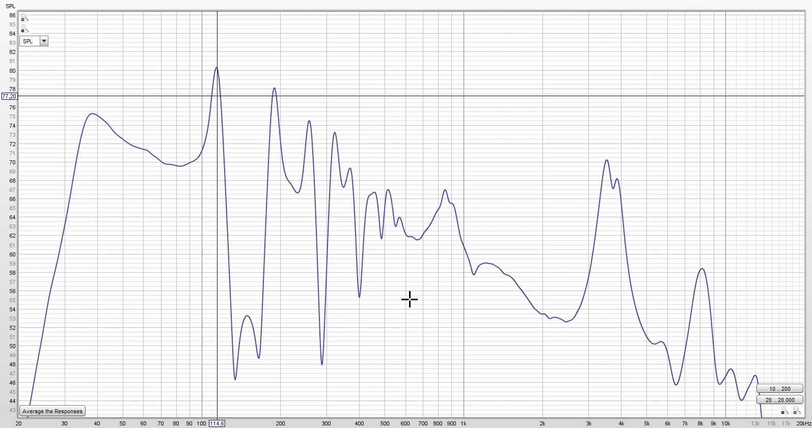
The response graph contains the whole frequency response chart. However, since this is nearfield measurement, only the section below 500 Hz is accurately measured. Since this is a subwoofer we are interested in the 20 – 200 Hz area anyway. So let’s analyze that :
- Reapeated peaks at 110 Hz, 190 Hz, 270 Hz etc. These are called resonant modes, and are specific to T-lines. Adding damping material in creative ways will solve this issue.
- Huge cancellation between 100 and 200 Hz. Making a DIY transmission line subwoofer box will surprise you with impressive dips in the response chart as well. Again, this can be solved with different types of damping material, placed in different quantities along the line.
- Somewhat usable frequency range (since this is a subwoofer) from 20 to 80 Hz, presuming that you don’t find offensive that +5 dB peak before roll-off. Also, you would need a very sharp active crossover to filter those unwanted resonant modes in the upper frequency range.
Conclusion
Making a DIY transmission line subwoofer with no aid from a computer app is basically pointless. You can start to add damping material to fix the issue, but doing so after the box is done is quite a challenge. It’s seems reasonable at the beginning and end of the line, but not somewhere in the middle.
You could argue that you can damp the line in the building phase. But what happens if that doesn’t work out? You can use different density or a different quantity to change things for the better. Again, hard to do when the box is finished. The normal approach is to use a program la Hornresp.
Promise that I will check this app in the future and see how it works and give this T-line anther shot.
You May also Like


Learn loudspeaker design from scratch

13 comments
The air is a fluid. The results are expected. In such a fragmented (squared) path the air could not move smoothly. So, that’s it. You need Caedium software for fluids.
Indeed you are right, those sharp angles won’t help in terms of how smooth the air circulates. However, this isn’t an issue of air turbulence, rather a phase issue. Reinforcement and cancellations between front and back waves.
ALL OK, BUT:
WHAT DIMENSIONS IS THE BOX ????
YOU NEED THE MEASUREMENTS TO MAKE IT.
THANKS AND INTERESTING WORK
THANKS Rino Italy
I didn’t include the measurements of the box, because it didn’t turned out well. It needs damping material on the inside to fix the unwanted peaks and cancellations. So I can’t really guarantee it will be ok if you do that. When I will learn hornresp and have a successful attempt, I will list all the details as usual.
Hello!
I’ve been doing some reading on transmission lines recently, and I stumbled upon an article just before I read this write up that I am curious could potentially help with the unusual resonances issue.
https://www.diysubwoofers.org/tls/
Long story short, I would be curious how the response curve would react to moving the subwoofer to a different place on the transmission line instead of simply on one end. Your design could potentially prove really useful to test the actual changes considering you have such nice square faces at each turn. Maybe just some food for thought! Thank you for documenting and sharing your experience!
Yea, most TL builds have the speaker placed somewhere near the beginning of the line, but not at the exactly at the start of the line (like I did). This does help with reducing cancellations and stuff. But still, if you don’t know how to use hornresp or some modeling software, you are still doing things in the dark and hoping for the best. Results won’t be guaranteed.
Easy fix , move the sub towards the top inner corner of the nice square its mounted in , 45⁰ all internal corners , kerf your t-line port , round over all open internal edges , spray with some acoustic sound deadner (second skin roll on is awesome for this , but a bit pricey) , at your 45⁰ ‘s and your inner front baffle , something else that will make a huge difference is angle your sub away from your t-line folded wave guide port end , that large square thingy that the subs rear sound comes from , lol, which could be a bit smaller
I would have really liked to have seen how well this box could have been made perform using stuffing, etc. It would have been interesting to see how much performance you could have extracted from such a simple, albeit flawed design.
Seems to be lots of flaws in the box to me, but that’s just me sorry it did it work for you .
But how was did the bass sounds to unique ?
It is exactly a real deep base from the T.line that bro
“Making a DIY transmission line subwoofer with no aid from a computer app is basically pointless.”
I started in an era where there was no Internet, and little access to complex equipment. But I do think people put far too much trust in overly simplified, basic software. For me, using hornresp and winisd didn’t yield good results when it came to listening.
Now I’ve development my own formula and software, that takes care of factors that those programs don’t cover.
T-lines in the right circumstance can be amazing. However, to simply design an arbitrary t-line, thinking it’ll work for all and any occasion, is going to give negative results in certain circumstance. There are plenty of projects where a t-line won’t be the answer, and plenty of drivers that personally I wouldn’t use for a t-line. I’ve had my share of failed projects!
Subwoofer Fs : 31.6 Hz
Wavelength = 343 / 31.6 = 10.85 m
Quarter wavelength = 10.85 / 4 = 2.71 m
The instructions are easy to follow. Make a line, at least the size of the woofer, which is 2.71 meters in length. The idea is to delay the back wave so that it’s no longer out of phase with the front wave.
Also, just looking at this, it seems your formulas and ideas of how to design a t-line are way off, I’ve never built a t-lines around the FS, and your design has too many bends. I only say that, because I’ve built something similar, 2 decades ago, but now, I try and limit the amount of bends there are.
Did you learn it yet? You’ve had four years. Should have your bachelors by now!