
Passive crossover network explanation
What is a passive crossover ?
Before we get deep into the passive crossover design, let’s start by splitting the crossover network into 2 kinds : active crossovers and passive crossovers. A crossover, regardless of its kind, will take the signal and split it into different frequency intervals or bands, and each band is routed to the appropriate speaker. For example : if you have a 2 way speaker, the crossover will route the low frequencies to the woofer and the high frequencies the the tweeter. See Fig 1 for an example of a 2 way crossover. Same applies if you have a 3 way or more system. The crossover will split the signal into as many bands as there are speakers. More speakers, means shorter intervals, and each speaker works with a narrower frequency range, thus a little less effort on each driver, for a multi-way setup.
- Passive crossover means that the signal is split after it is amplified by the amplifier. For this reason, it has to deal with large currents and voltages.
- Active crossover means that the signal is split before it reaches the amplifier. Which means the crossover works with a low level signal, but for each driver of the system a separate amplifier channel is needed.
The active crossover
It has many advantages versus the passive crossover, but it is more complex to build and requires more amplifier channels to drive the system. While the passive crossover has fewer components, it is more difficult to design. There is more to it than just splitting frequencies. The crossovers need to correct some frequency response imbalances of the drivers, the roll-off slopes need to be on point, so that the transition between low and high frequencies, at the crossover point, is done as flat as possible, with no response dips or peaks, phase corrections etc. Nevertheless, a crossover will make or break a high quality speaker.
Here is a graphical explanation of the active and passive crossovers :

For the rest of this article we will focus on the passive network. Although it has its disadvantages, it is more convenient and more widespread.
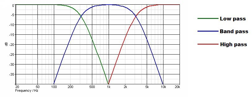
Depending on the frequency it filters, the crossovers are split into 3 categories :
- High pass filter : Filters the low frequencies and lets the high frequencies pass. Used for tweeters
- Band pass filter : Filters some low frequencies and some high frequencies. Used for midrange drivers.
- Low pass filter : Filters the high frequencies and lets the low frequencies pass. Used for woofers.
Properties of the passive crossover
The passive crossover is a circuit board on which you will find capacitors, inductors and resistors. The main characteristics of a crossover network is its inductance (L) and capacitance (C). The inductance and capacitance are frequency dependent, and on different frequencies, they provide a different AC resistance or reactance :
- Capacitive reactance is inversely proportional to frequency => Capacitors provide more AC resistance as frequency lowers
- Inductive reactance is directly proportional to frequency => Inductors provide more AC resistance as frequency increases
How to design loudspeakers - video courses


There are 3 properties that describe a crossover :
Filter resonance
This describes the frequency where the component reactance are equal. It is the actual crossover frequency / crossover point. The formula which dictates the crossover frequency is dependent of (L x C). If you give different values to L or C, but their produce is the same as before, the crossover frequency remains the same.
The slope of the roll-off
This describes the attenuation, measured in db / octave. Near the crossover point, the frequency response will start to roll-off. Depending on the components used in the crossover network the roll-off can be gentle or steep : 6, 12, 18 or 24 db / octave. Sometimes more than 24 db/ octave, but very rarely. The type of slope dictates the order of the crossover :
- 1st order : 6 db / octave slope
- 2nd order : 12 db / octave slope
- 3rd order : 18 db / octave slope
- 4th order : 24 db / octave slope
Q
This describes the shape of the “knee” when the frequency starts to roll off. The Q shapes are exactly the same as Qtc discussed at closed box. This means that a Q=0.7 will give somewhat a flat knee before roll-off, while a Q=1 will give a slight peak before roll-off. Also, the different values of Q have different names, corresponding to those who pioneered these response shapes :
- Q=0.49 => Linkwitz – Riley
- Q=0.58 => Bessel
- Q=0.707 => Butterworth
- Q=1 => Chebychev
These names should be remembered, because they are mentioned in passive crossover descriptions. For example : LR4 means a 4th order Linkwitz – Riley crossover.
Explanation of terms
The next graph is a 2 way passive crossover with a visual description:
- Low pass (the orange–blue–brown line) describes the frequency which is going to be player by the woofer
- High pass (the green line) describes the frequency which is going to be played by the tweeter
- Pass band (orange line) describes the frequency on which the crossover does not interfere. It lets these frequencies pass. While not shown in the graph, but using analogy and common sense, another pass band is present for the high pass as well.
- Knee (blue line) describes the point where the effects of the crossover are kicking in. The frequencies are attenuated starting from this point. Q dictates the shape of the knee. It can be smooth (like in this graph) or it can have a small peak (for Q=1 for example)
- Crossover point (yellow dot) : The point where high pass meets the low pass. In a practical example : if the crossover point is at 500 Hz, the woofer will receive 20 – 500 Hz and the tweeter will receive 500 – 20 000 Hz.
- Octave : An octave is any frequency range which ends in double of what is started : 20 – 40 Hz is an octave, 40 – 80 Hz is an octave, 2500 – 5000 Hz is an octave etc
- Slope (brown line) : The amount of attenuation per octave, starting from the crossover point. In our case, for each increasing octave, it looses 12 db of output. Judging by our graph, let’s say the crossover point is at 350 Hz. Let’s say the woofer is 90 db loud at 350 Hz. Because of the crossover attenuation and the 12 db slope, the woofer will be 78 db loud at 700 Hz, 66 db loud at 1400 Hz and so on.

Crossover point
You must be looking at this graph and being like : Wait a minute !? What’s with the dip at the crossover point? Shouldn’t the frequency response be flat ? Yes, it should, and it will be flat, if the crossover is made correctly. Let me give a practical example on our graph : Lets’ say the woofer is 90 db loud at 20 Hz and plays alone at this frequency. The tweeter is 90 db loud at 4 Khz and plays alone at this frequency as well. At 350 Hz (the crossover frequency), the woofer is 84 db loud and the tweeter is 84 db loud as well, but they play both at the same time.
When 2 sound sources play the same sound and are in phase, it will combine for a +6 db louder sound. So, the woofer compliments the tweeter at the crossover point to make a smooth transition and yield a flat response (of 90 db). To choose the correct crossover point, so that the sound system will be flat, phase is a determining factor.
How to design loudspeakers - video courses
Phase
Phase is important because when the sound of speakers add up, they do in different ways according to phase. If two speakers play the same sound and are in phase, they will combine for a + 6 db sound level increase. But what happens when the 2 are out of phase ?
How does sound add from 2 sources according to phase (lets consider both are producing 90 db of sound output) :
- 90° out of phase : When 2 sources are 90° out of phase, they sound like they are producing different sounds. This will add up for a +3 db sound increase, so 93 db of total output. Imagine 2 people shouting at the same level but shouting something different. They will sound louder together, no ?
- 180° out of phase : When 2 sources are 180° out of phase, they will cancel each other out, so 0 db of total output. If you reverse the polarity of the out of phase speaker, it will be in phase and this will result in +6 db of sound output, for a total of 96 db.
- 360° out of phase : When 2 sources are 360° out of phase, it’s the same as they would be in phase. This will add up to + 6 db of sound increase.
Crossover types and phase relationship
Why is this important? Because using different types of crossovers will result in different phase relationships between the drivers. So if the drivers are 90° out of phase, the crossover point needs to be -3 db. When the sound of the woofer and the sound of the tweeter combine, it will result in a flat response. If the drivers are 180° or 360° out of phase, this means that the crossover point needs to be -6 db, to get a flat response from the overall sound system.
Different filter Qs and slopes have different phase characteristics :
- 1st order and 3rd order Butterworth present the high pass and low pass in a 90° out of phase relationship
- 2nd order Linkwitz – Riley, Bessel, Butterworth and Chebyshev present the high pass and low pass in a 180° out of phase relationship
- 4th order Linkwitz – Riley, Bessel, Butterworth and Chebyshev present the high pass and low pass in a 360° out of phase relationship
Time and phase delay
All of the information we just talked about doesn’t take into account the positioning of the drivers. We are assuming that the drivers radiate sound from the same spot. This does indeed happen for coaxial drivers, where the tweeter is mounted on a pole in the middle of the woofer. This way, the sound from both speakers come from the same acoustical center. In most cases, the woofer is separated by the tweeter. Usually, the tweeter is on top and the woofer is on the bottom, with some distance between them.
Vertical alignment
This vertical separation creates some problems. At the crossover point, where the frequency response of the woofer overlaps the frequency response of the tweeter, it could create some time delay and phase distortion. To minimize this issue, reduce the distance between the woofer and the tweeter as much as possible. However, knowing what the crossover frequency is, you can find its corresponding wavelength at that frequency (in meters). Make sure the distance between the two drivers is not longer than that.

Horizontal alignment
Another thing to take into account is the horizontal separation. The acoustical center of each driver is considered to be in the middle of the voice coil. The voice coil is sitting right in the magnet assembly. Imagine how shallow a tweeter is and how deep a woofer is. For this reason, it creates an horizontal separation between the acoustical center of the woofer and the acoustical center of the tweeter. Even though the tweeter is on the same baffle as the woofer, it is actually in front of the woofer, acoustically. To correct this, you can use an asymmetrical baffle, to place the tweeter a little bit back, so the coil of the tweeter is on the same plane as the coil of the woofer.

These distance differences should be taken into account when designing the passive crossover network, as it can correct them or make them worse. In conclusion, the placement of the drivers and the phase behavior of each driver should not be neglected.
Conclusion
This article does not tell you how to build a crossover or what are the physical components of such device. The crossover is a vast subject and this article is only trying to cover the basics of the passive crossover. However, in future articles we will tackle this subject in depth, with instructions of how to build different types of crossovers as well.
References
- Loudspeaker Design Cookbook 7th Edition by Vance Dickason (Audio Amateur Pubns, 2005). (Amazon affiliate link)
- Introduction to Loudspeaker Design: Second Edition by John L. Murphy (True Audio, 2014). (Amazon affiliate link)
- Image source : link.
You May also Like


Learn loudspeaker design from scratch

5 comments
Thank you for this clear and precise explanation! I find your Udemy course and your articles very helpful and informative. I do not have a background in engineering,. This means that I find most books about acoustics quite hard to digest. Since I have started your online course and reading the information on this website I have learned so much. Now I am more confident that I can start reading the more in depth and complex books in the future!
Hi, in the section on crossover types and relationships you say: 2nd order Linkwitz – Riley, Bessel, Butterworth and Chebyshev present the high pass and low pass in a 180° out of phase relationship. In the related article called Passive Crossover Schematic, it suggests that for second order filters: Butterworth has 90 degree phase difference which means the 2 curves will add up for 3 dB boost. However, Linkwitz-Riley has no phase difference and the 2 curves add up for a 6 dB boost. Does 2nd order LR have a phase shift?
All crossovers introduce some amount of phase shift. All 2nd order filters have 180 phase shift, so wiring the speakers out oh phase will nullify the phase shift. Butterworth has the crossover point 3 dB below linear, so when you add the 2 curves together (+6 dB at crossover point) you will have + 3 dB above linear response (that 3 dB boost you mention). Linkwitz Riley has the crossover point 6 dB below linear, so when you add the curves together you get a perfectly flat response. At least that is the theory …
I tried various things.
It’s best to connect a 40cm low range and a 2370A + 1 inch driver at 800Hz. It was
In this case, it is kind to the driver to connect the low range with 6db and the high range with 18db.
Can you create such a network?
Yep you can. In fact, it’s most likely to have asymmetric slopes. The theory and basic crossover formulas consider the speaker as a resistor with fixed resistance. But in reality the speaker has variable resistance with frequency. So, in real life things get complicated and having different order filters for the woofer and tweeter is quite ordinary.