
6th order bandpass box design – using JL 10W6v3
How to make a 6th order bandpass enclosure?
Choosing a 6th order bandpass box design for your woofer is definitely a more exotic approach to enclosure building. These types of boxes are pretty rare, because of obvious reasons. First of all, there isn’t much information about this design. Mainly because Bose has a patent on this type of enclosure. You cannot build a 6th order bandpass box commercially. However, there is no problem if you build one for personal use. This might be the reason why I haven’t found any BP6 alignments in the audio literature (I was hoping for something similar to bass reflex alignments). Nevertheless, you can use box design software to model the frequency response (I used SoundEasy).
Let me think about other reasons why you seldom see this kind of speaker boxes. They have little tolerance for error. If you have a tendency to do designing or building mistakes, you are better off looking somewhere else. Slight errors can translate into serious misalignment. Some might be put off by the sheer size of the cabinet. While a large box is impressive, and it’s nice to show it off to your friends, no one wants to put up with the hassle of owning one. The transient response of bandpass enclosures isn’t great also. This is pretty much true, regardless of how you tune them.
However, on the plus side, the 6th order bandpass box design has a very high efficiency rating. It has the potential to hit really hard and go really low in frequency. And who doesn’t like loud, deep bass? The whole point of this article is to show you how to do that using a JL 10W6v3 (Amazon affiliate paid link) woofer.
6th order bandpass box design for the 10″ JL woofer
First of all, like any bandpass enclosure you need to set your priorities. You have to choose between efficiency, linearity and frequency response bandwidth. To give you an example : If you want the box to be able to play a broad frequency spectrum, it will not be as loud. As a result, if you gain something in one department, you have to make a compromise in some other department.
The design philosophy of this enclosure design : I want it to be loud, with linear response and go very deep (below 30 Hz). Hopefully, the response will go decently high in frequency. Because this is where we will pay our tribute, to the playable frequency spectrum. It will go up to at least 60 Hz, perfectly flat. In conclusion, it will play the lowest notes, really loud. A true “sub”-woofer.
Let’s take a look at the modeled frequency response. The actual measured response looks even better. That will be at the end of the article.
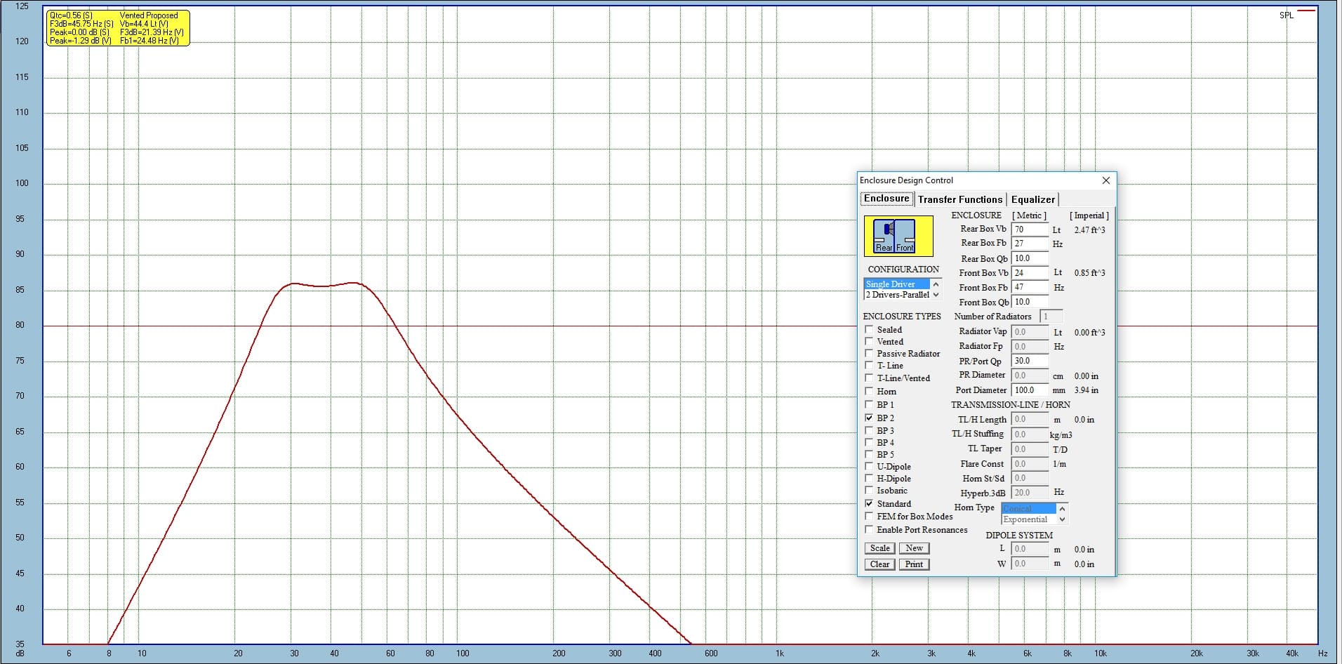
So we can see the numbers here :
- Front chamber volume : 24 liters.
- Front chamber tuning frequency : 47 Hz.
- Rear chamber volume : 70 liters.
- Rear chamber tuning frequency : 27 Hz.
These are the net volumes. After adding the port volume, the volume displaced by the speaker and the brace, chamber size increased a bit. Front will be 26 liters and rear will be 75 liters. Now that you have the volumes and tuning frequencies you can design the box as you see fit. I did it according to my trunk space, but you can alter the dimensions as you see fit, as long as you keep the above values the same.
Port design
To tune the chamber, we will use 100 mm circular ports, flared at both ends. The ports I used were Jantzen Audio 100 mm bass reflex ports. You can find more info about them here (scroll to the bottom). I know that Precision ports are more popular in the US (like this one (Amazon affiliate paid link)), but I’m sure you can cut them to the same size and get almost identical results. The expansion rate of the flare might be a bit different, but that will have a negligible impact on the overall result.
How to design loudspeakers - video courses


The modeling software tells us that the ports need to be 388 mm long for the rear chamber and 371 mm long for the front chamber. These lengths are for a basic, straight pipe. However, the subwoofer is capable of moving large amounts of air, so having a flare at both ends of the pipe is mandatory. This will ensure a smoother air motion through the port, but it alters the port length to some extent. More on that later, when we do the actual build.
Panel dimensions
To make the box, I used 22 mm MDF. Some people, might consider this overkill for a 10″ woofer, but that’s how I like it. Indeed the box is extra heavy, but in audio, that’s a good thing. If you want to use 18 mm MDF you have to adjust the sizes of the panels to keep the volumes the same. If not, just follow my design.
Panel list :
- 727 x 510 mm -> 2 pieces (top and bottom).
- 727 x 334 mm -> 2 pieces (front and back).
- 554 x 334 mm -> 2 pieces (sides).
- 510 x 294 mm -> 3 pieces (double baffle and internal brace).
Here is a diagram with all the panels for a more comprehensive view. Also, you find here the sizes and the positions of the holes for the speaker and the ports.
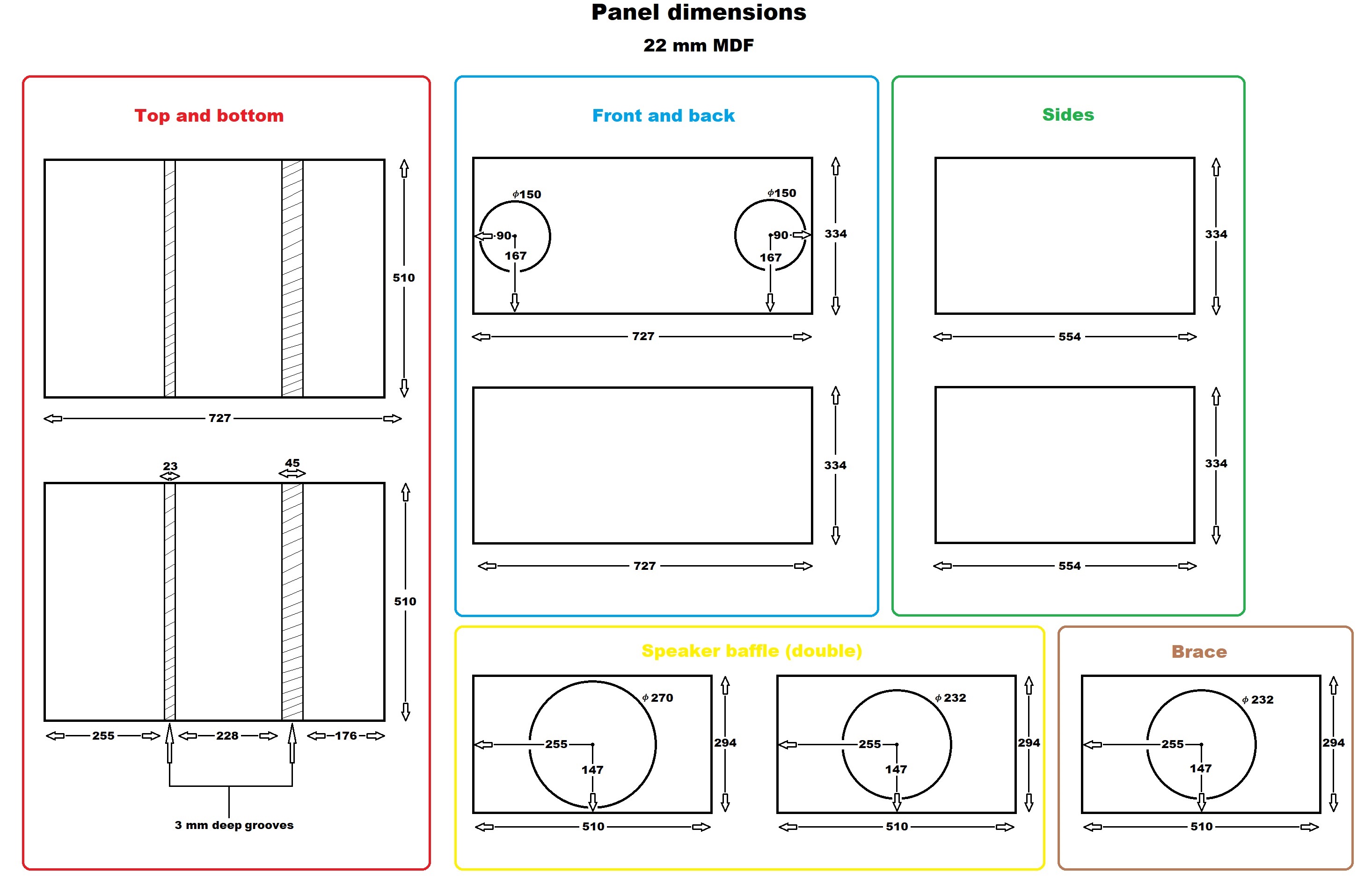
The brace and the speaker baffle panels have an additional 4 mm in width (or should I say height). I’m going to make grooves in the top and bottom panel, so these panels puzzle up together. The speaker baffle and brace have 2 mm extra for the bottom groove and 2 mm extra for the top groove. The grooves are 3 mm deep to allow some space for the adhesive.
Build guide
I’m going to give a step by step process on how to actually make this 6th order bandpass box design for the JL woofer. For the sake of it, I’m going to include a lot of pictures with the process. Good in terms of visual aid, bad if you are on your phone with a limited internet plan. So let’s begin.
Creating the grooves
We need to make 2 grooves on the top and bottom panel, so we can puzzle in the baffle and the brace. The brace will be 22 mm wide, and the double baffle, 44 mm. To give some wiggle room, make sure the grooves are 1 mm wider, so 23 and 45 mm. The depth of the grooves should be 3 mm.
Align the top and bottom panel, and use 2 large clamps to secure them in place.


Now, use an Emerson tool (Amazon affiliate paid link) (straight edge clamp) and a router to make the grooves. Set the router at 3 mm depth and calculate the exact spot you need to place the Emerson tool in order to make the groove in the right place. The router will usually have a 6 mm bit, so you need to make multiple cuts to make the 23 and 45 mm groove. First, cut the beginning and the end of the groove, and then cut in between. Check the panel schematics again to see where the grooves go.


Tedious part over. Let’s get to some circle cutting.
Baffle, brace and front panel
We need to cut some circles in the baffle, the brace, and the front panel (to accommodate the ports). For the baffle and brace, the center of the circle will be in the center of the panel. So, to not make any measurements, I like to draw two lines from the corners. Where they intersect, it marks the center of the panel.

Now, to cut the circles, you have the dimensions in the schematic at the beginning of the article. But most likely you will use the Jasper circle jig (Amazon affiliate paid link). Here are the dimensions for the jig :
- Outer baffle : 10″ + 10/16″
- Inner baffle : 9″ + 2/16″
- Brace : 9″ + 2/16″
- Port hole : 5″ + 14/16″
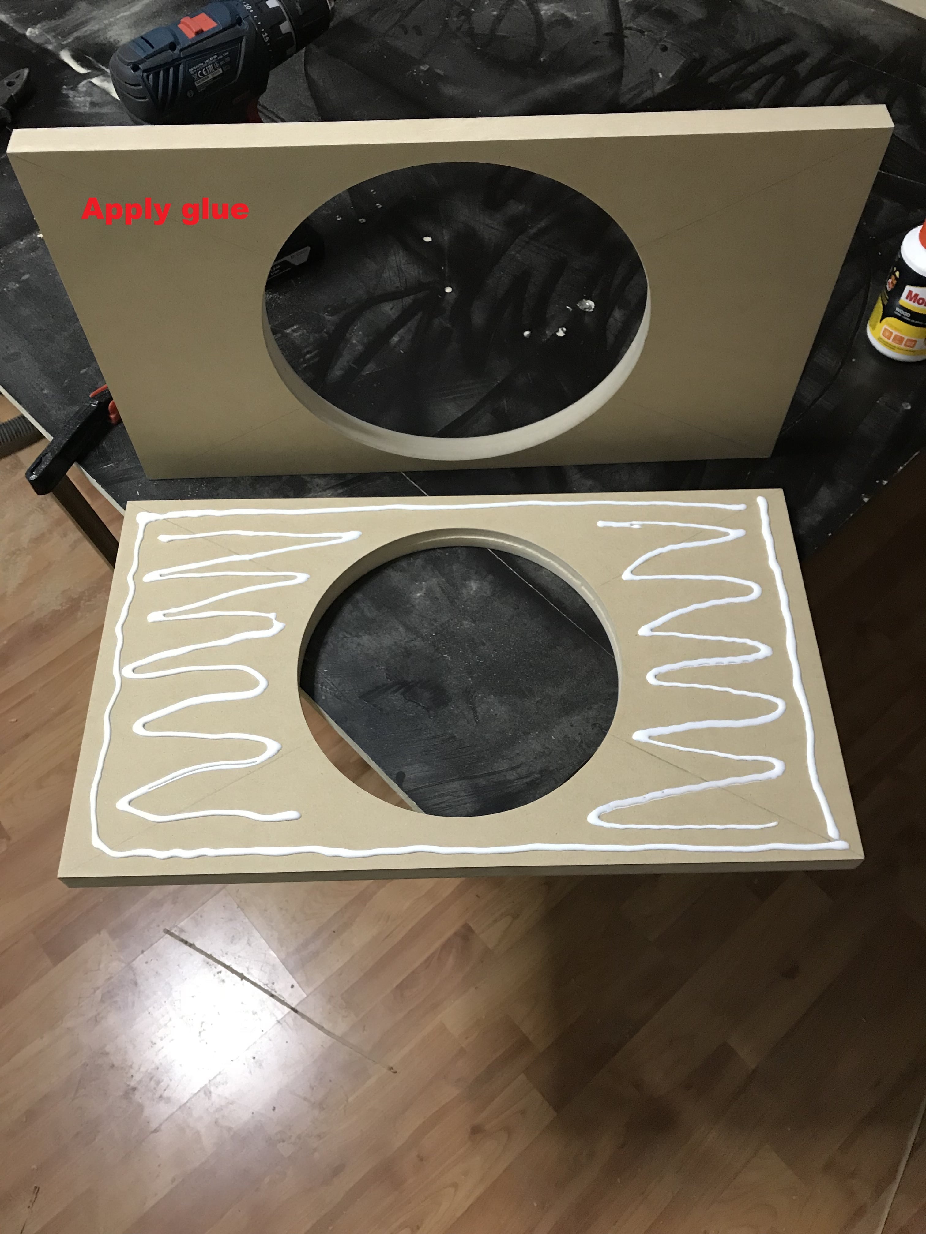
After the circles are cut, we need to stick the 2 boards together to make a double baffle.


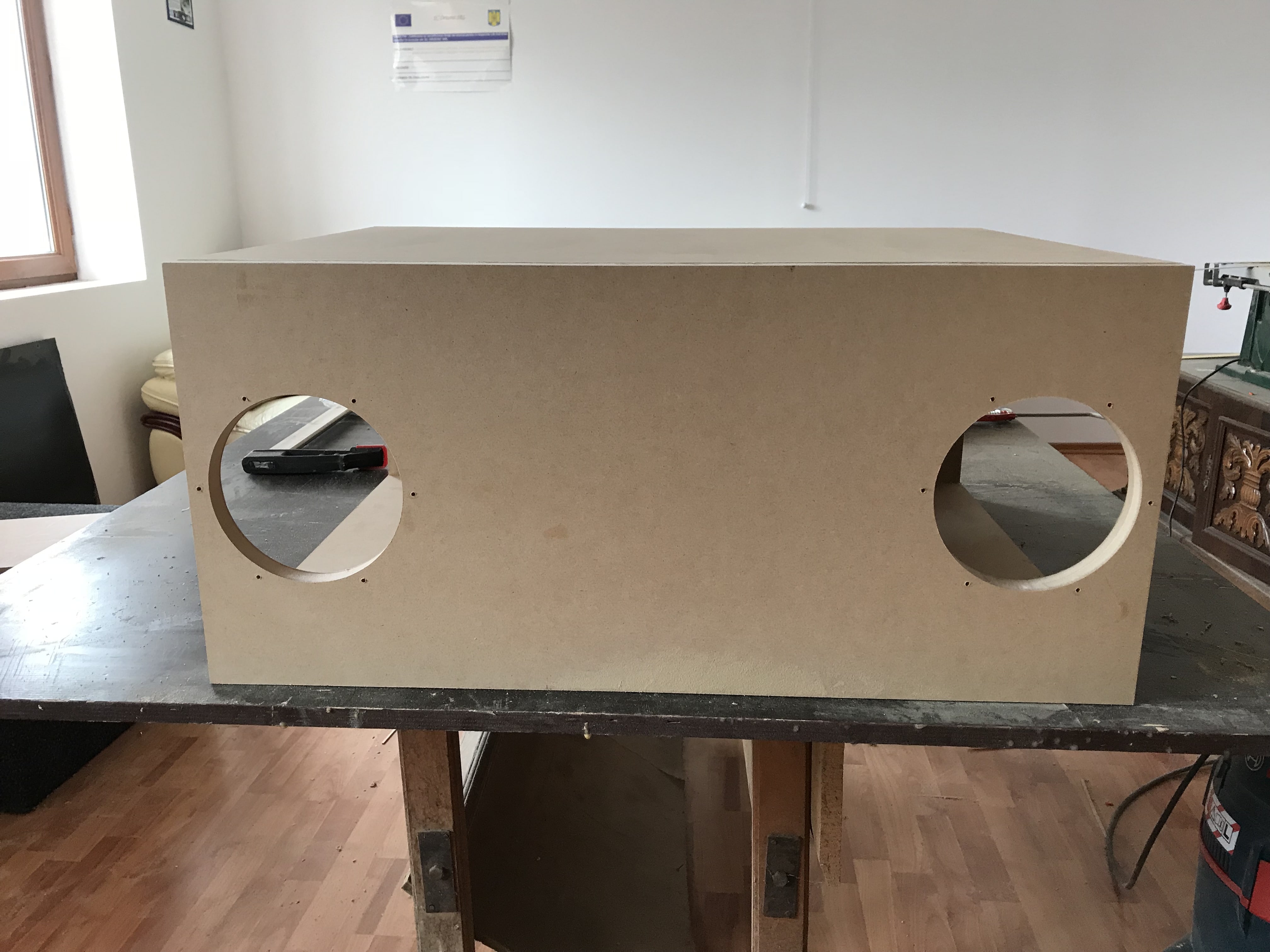
Now it’s time to focus our attention to the front panel. The holes need to be cut halfway height-wise, and 90 mm away from the edge (I’m talking about the position of the center of the circle).

Assembling the box
Now that we have all the pieces cut to the correct size and shape, the next step in our 6th order bandpass box design, is to start puzzling the pieces together. Get the wood glue, some clamps and a friends to help you out.


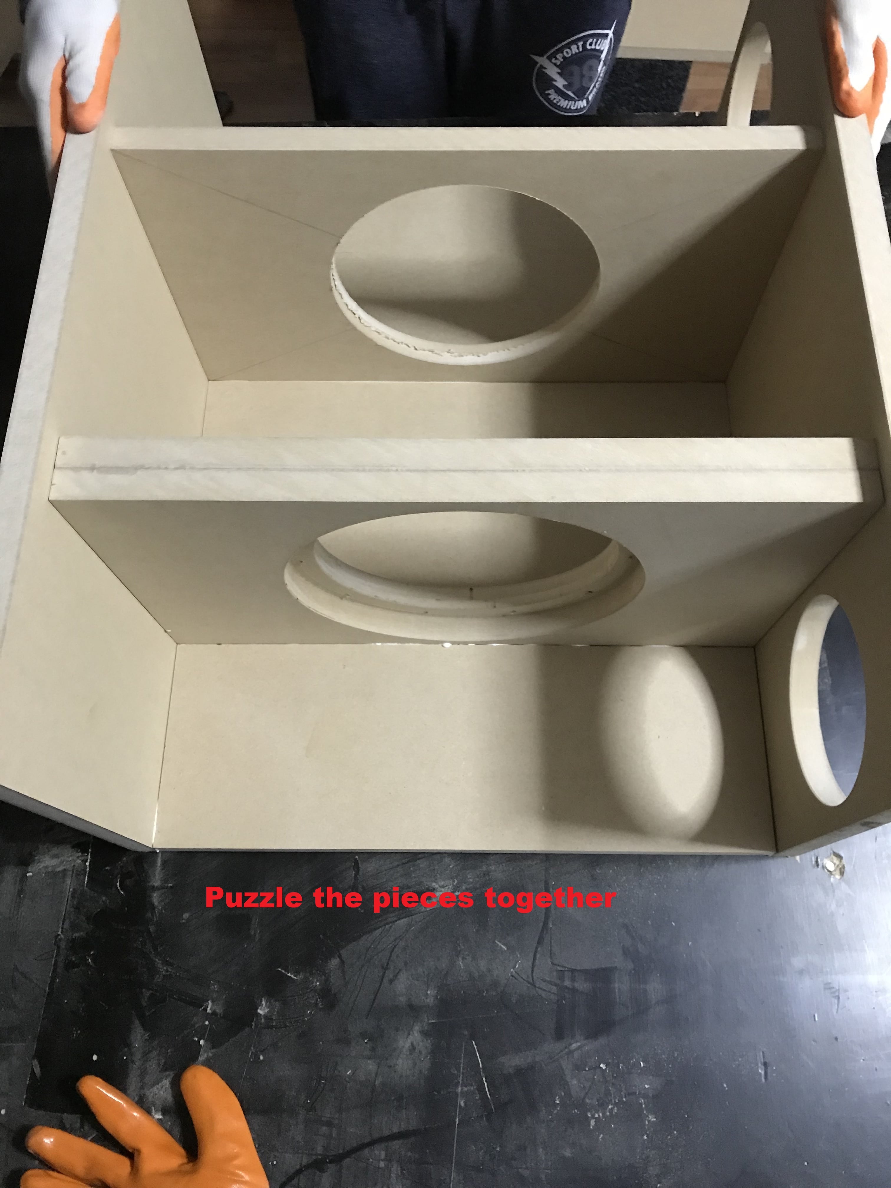
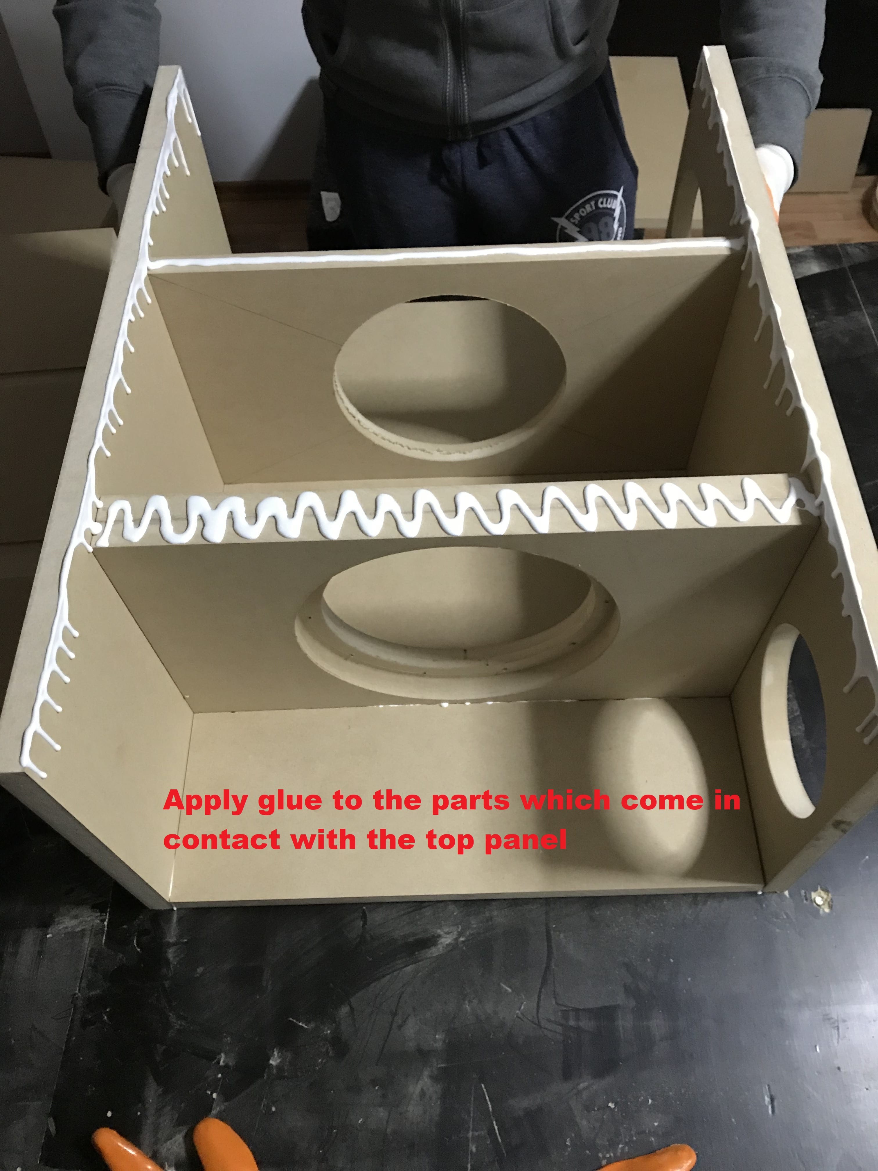


As you can see, all the panels are in place except for the sides. Problem with the 6th order bandpass box design is that the speaker is inside the cabinet. Once the box is finished you don’t have access to it. I managed a solution. Check it out in the next section.
The side panels
I didn’t fit the side panels to the box yet, because I want to adopt a different solution on how to integrate them in the box. If I were to use wood glue, the only way to take the speaker out, is to destroy the whole box. While this might not be an issue, if you opt to cut the box open, the sawdust might reach the voice coil and do permanent damage.
For this reason, I will use screws and abundant silicone sealant. If you want to take the speaker out, simply unscrew all the screws and pry the side panel open using a crowbar.
First, position the side panels in place using large clamps and the pre-drill the holes for the screws . Don’t make a hole right next to the port cutout!


Before you place the side panel, let’s drill-in the binding posts and connect the cables that will go to the speaker.


Now all you have to do is place a lot of silicone and screw the panel in place.

Do the same for both panels. Make sure to let it rest for a whole day, so the silicone cures.

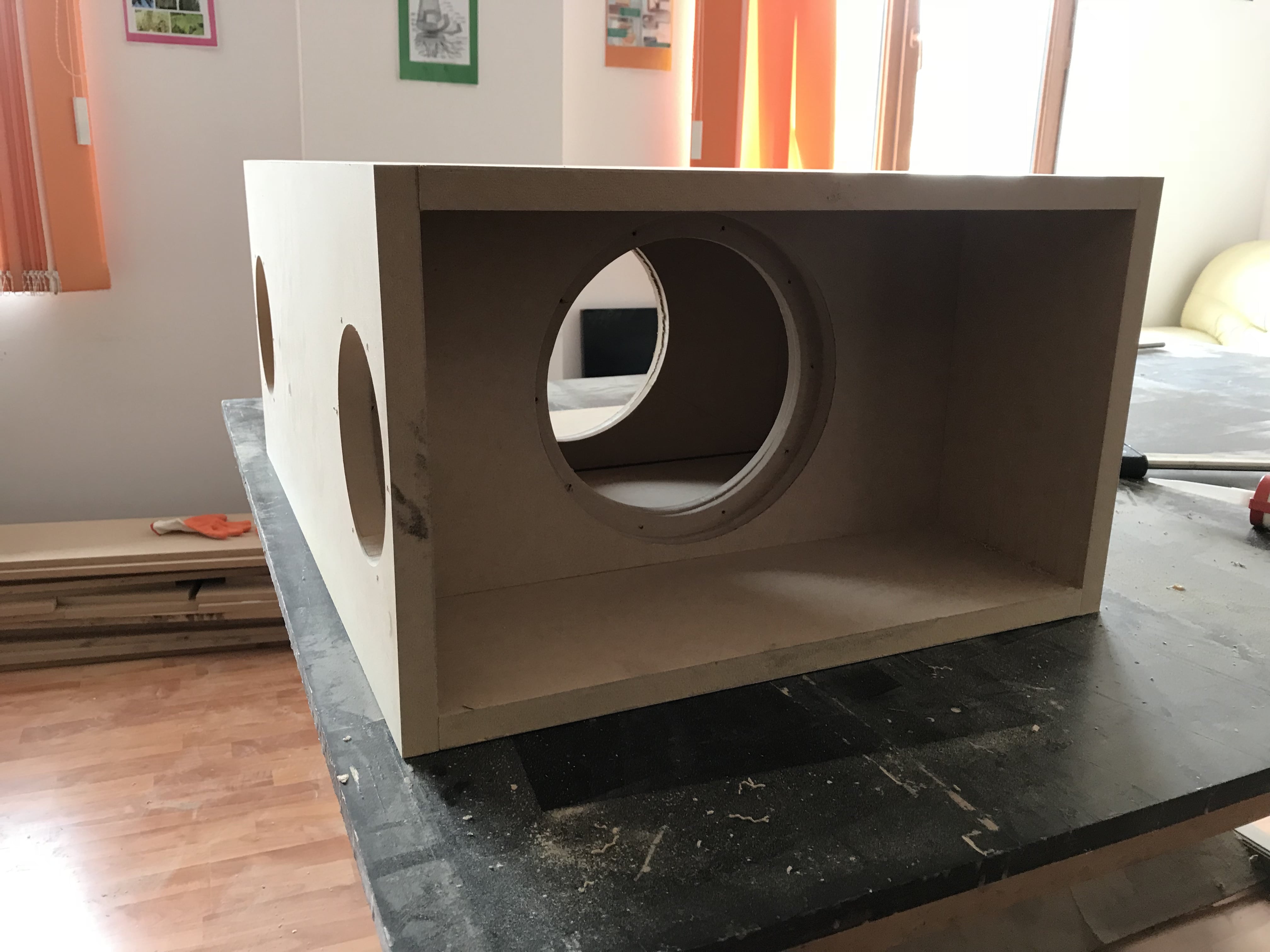
Above you have the box with all the panels in place. I also used silicone on every inside joint, before placing the side panels and after.
Port adjustment
The ports come with a 400 mm long pipe and they need to be adjusted to size. I’m going to give you both the dimensions of the bare pipe, and with the flares attaches.
- Front chamber (small one) : the pipe is 343 mm long, and with the flares attached – 415 mm.
- Rear chamber (large one) : the pipe is 351 mm long, and with the flares attached – 423 mm.
Here are some pics, so it’s more clear :


After you cut the ports to size, apply abundant silicone sealant. I always like to go overboard here, but I don’t want to risk any port distortion.
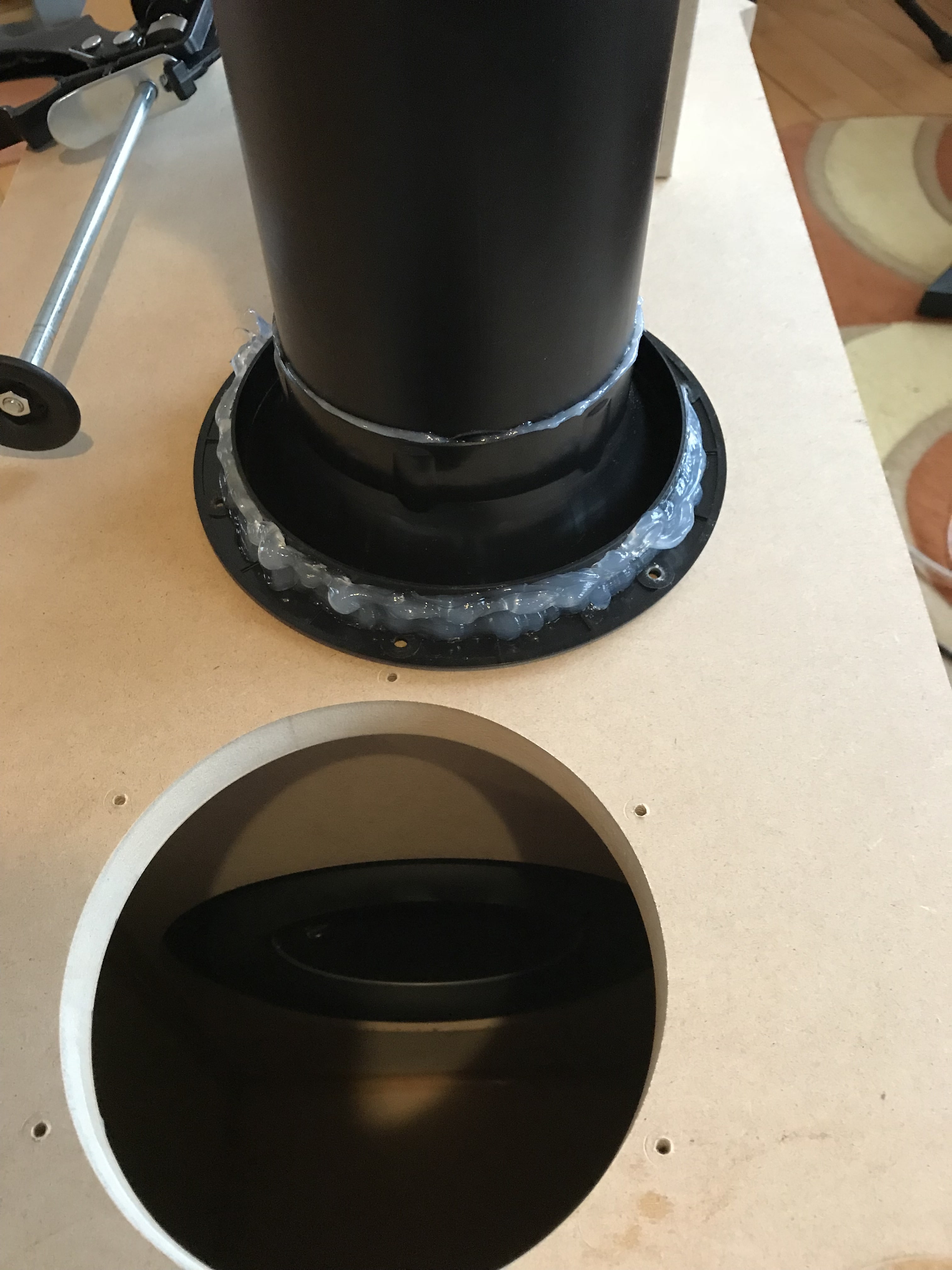


I know the quantity of silicone looks like overkill, but you can remove the excess after it has cured. Screw the port screws and let the silicone completely dry out for a whole day.

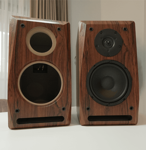
Here is the finished box. I made this 6th order bandpass box design just out of curiosity. You can see the sealed box next to it, which is empty. It will go back there, soon enough.
Results
Let’s do some measurements and see how this 6th order bandpass box design stacks up.
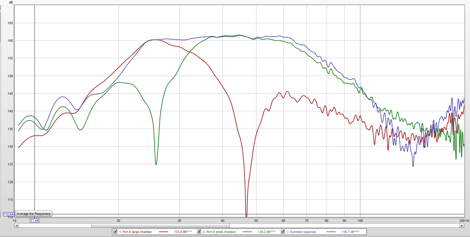
Above you can see the responses of both ports and the combined response. What’s interesting to note here, is the 2 dips. Each port has a dip in its response. That dip marks the tuning frequency of the other port. As you can see, the port in the small chamber has a dip at 27 Hz. In conclusion, 27 Hz is the tuning frequency of the larger chamber, and vice-versa.
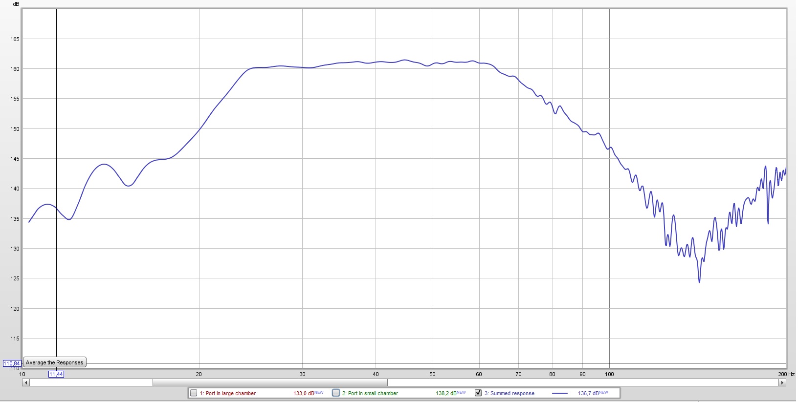
Above is just the combined response of the 2 ports. Or the response of the box as a whole. We have an almost ruler flat response on the pass band :
- Frequency response : 24 Hz – 63 Hz (+/- 1 dB).
- Frequency response : 23 Hz – 72 Hz (+/- 3 dB).
Very pleased with the frequency response.
Conclusion
The 6th order bandpass box design is not for everyone. Indeed it has its drawbacks. But for a 10″ woofer the output is absolutely insane, it drowns my mids completely. Listening to it full blast for 30 seconds, hurts my ears for an hour. If you got the mids and highs to warrant this type of enclosure, and you don’t mind the space issue, you might as well give it a try.


Learn loudspeaker design from scratch

67 comments
That looks really nice! The more exotic style boxes seem to be more fun.
I just bought this exact JL sub.
So is it fair to say that this box will hit lower than most frequencies?
Well, yeah, you can see from the frequency response chart. However, bare in mind that this enclosure is quite big. Sounds awesome though.
Thanks for the reply. I see JL builds a factory enclosure and sells it with the sub. It’s a ported box I think. If you had to build another box for the same sub would you change anything?
Like would you do slot ports vs the vent tubes?
It’s kind hard to get the slot ports right. Because after you build the box and measure it, and it’s not the response you want, you cannot alter the ports. Anyway, the box is awesome, except for the fact that the overall size is huge.
First off thank you for your work and passion for car audio. I am hoping to take one of your classes soon and to become proficient in designing all of the various enclosures, especially the exotic boxes. Wondering if you could help. I just bought a Soundqubed hds 3 – 10″ subwoofer and Wondering if you could design a 6th order bandpass with the same design parameters as you built your box.
F(s) 37 Hz
Impedance D2
Z(max) 93.81
Q(ms) 6.869
Q(es) 0.611
Q(ts) 0.561
V(as) 8.328 liters
L(e) 0.851 mH
n(0) 0.13 %
M(ms) 235.7 grams 364.40 grams
C(ms) 0.05 mm/N
Sensitivity 1W/1m 83.24 dB
BL 29.36
6th order bandpass gets misaligned really easy. You need to design a specific BP6 enclosure for your driver. You can’t use this one.
Hey Marius,
Really appreciate your work and YouTube channel. Learning how to make my audio better because of your videos and articles. Question, I just got a JL AUDIO 12W6V3 and I am wondering if you could help me to design this same box for it. I can pay a bit for your time. Please let me know. Thanks.
what is the program?
Don’t know exactly to what are you referring.
The program used to model the box response is SoundEasy and the one used to make the measurement was Romm EQ Wizard (although you can use SoundEasy for measurements as well, but it looks nicer in room eq wizard)
if I want a 6th design for playing for only low frequency and not loudness which one do I choose between efficiency, linearity and frequency response bandwidth ? 95% of my music have low notes like decaf
You need to model the response for your exact speaker. If you want to sacrifice loudness, you gain a broader playable frequency bandwidth. Also, the box will be smaller.
hi,
i have 8 inch driver with following spec . is it possible to calculate box for me ?
i could not able to find solid design calculations online.
Sensitivity (2.83V/1m)90 dB
Resistance (DC)3.5 Ω
Qms5.48
Qes0.33
Qts0.31
VAS33.89 Litres
fs=30hz
Rear chamber 60 liters tuned at 27 Hz (port 75 mm diameter, 248 mm in length). Front chamber 20 liters tuned at 48 Hz (75 mm diameter port, 232 mm in length). These are net volumes, add everything that takes up space (volume displaced by back of the speaker, port tube, braces etc).
Can u help with enclosure for 2 12″ digital designs redline 712d2
Space isnt issue
TS
Fs: 37.68
Qms: 5.99
Qes: 0.521
Qts: 0.479
Vas in liters 20.161
Thanks for help
Here is a possible solution :
Rear chamber 60 liters tuned at 29 Hz (300 x 40 mm port with 620 mm in length).
Front chamber 19 liters tuned at 65 Hz (300 x 40 mm port with 360 mm in length).
The volumes are net volumes (add the volume displaced by the speakers, ports etc).
I’ve been searching for the designs of 6th order builds and now I know why I can’t find any. But when I get 15 ready for a build I’ll check back. Great article I liked it!!
Oh, when I say with the same parameters as the box for the JL audio I simply mean when you made this statement…. I want it to be loud, with linear response and go very deep (below 30 Hz). Hopefully, the response will go decently high in frequency. Because this is where we will pay our tribute, to the playable frequency spectrum. It will go up to at least 60 Hz, perfectly flat. In conclusion, it will play the lowest notes, really loud. A true “sub”-woofer. I understand that it cannot have the same dimensions as the JL box. Sorry for the confusion.
Your driver doesn’t really work that well in a BP6. If you really want to do it then I suggest the following :
Rear chamber of 60 liters, tuned at 30 Hz (10 cm diameter port of 36 cm in length)
Front chamber of 15 liters, tuned at 55 Hz (10 cm diameter port of 45 cm in length)
These are net volumes. Add anything else that displaces volume (rear of speaker, port tubes, braces etc)
Yes Sir, thank you for the great articles and the awesome website. I know it’s a thankless job posting enclosure specs for random people online, but if you’d be kind enough to take a guess at this it’d be very much appreciated! I’ll post pictures after I build it this weekend. It’s a single 18″ and I’m looking for a parallel 6th order, FR from 25-60hz. Here are my specs-
FS: 31.2 DCR: 1.4/coil QMS: 7.76 QES: 0.31 QTS: 0.32 MMS: 338 SD: 1210 VAS: 139.3 SPL: 94.5 BL: 25.2 XMAX: 29 POWER: 2250w RMS
Thanks so much!
You got one chamber of 80 liters tuned to 25 Hz (150 mm diameter port of 950 mm in length), and the second chamber 40 liters tuned to 60 Hz (150 mm diameter port of 260 mm in length). Cheers!
Excellent write up! I enjoyed it very much! Plan on doing one for my dd recline 610 d4 if I can figure it out. Thanks!
Great work!.. looks really good and your assembly process was also super clean and well done. You should be happy as a pig in it on this one brother- very nice.
I’m interested in a 6th order for 1 jl audio w7 13 .mostly all frequencies a 6th order will play strong meaning 28hz to 75hz.
Awesome write up . I have an older JL 10w6v2-D4 and would like to try it. What would the volumes be for this ? Fs 28.5 Qes 0.497 Qms 8.458 Qts 0.469 Vas 33.4 L Xmax 15.2mm Efficiency 83.7 db Sd 0.0332 m sq
I was going to build it as a center rest so port area would be useful as well in case of design issues.
Thank for the help !
I just punched in the numbers, and even if you use the same enclosure as I did (for the new JL driver) you will get very similar results.
If I were to design an enclosure specifically for your driver, the only modification I would do is to tune the rear chamber to 26 Hz, instead of 27 Hz. And the rest keep the same. You can imagine that there is barely any difference. Just make the same enclosure you find in this article and you’re good.
Thanks again for your help on this .. I will tune the rear chamber to 26 Hz , what is the new length of the port ?
Make it 3.5 cm longer than the one stated in the article.
ey just wonderin you place your port on the same side the sound will be out of phase im pretty sure about that thanks
If that would be the case, you would have massive cancellation and the frequency response won’t look like the one posted in this article. But just so you know, the placement of the port doesn’t account for much. You have to realize that we are talking about bass frequencies, with a wavelength of 5+ meters. So even if you try to spread them out, if they were out of phase (180 degrees), you would have no bass.
HI Marius,
I am looking for a 21″ bass Reflex Design for PA System use/hire. I will be looking to make up to 8 cabinets = 4 per stack. I am looking for deep solid thump of bass from 30 up to 120/150hz.
There are two possible drivers:
B&C: 21SW115 or
Celestion: NTR21-5010JD
Can you help me with the design please?
Shaun
I answered you on udemy. We will talk there
Could you help out with 2 of my builds? Would like your opinion. One now, one in the future. Would be awesome of you:)
Yeah, sure. I’ll be happy to help.
I’m also building a similar box for a 10w6v2. How did you choose the two tuning frequencies for the front and rear chamber?
I tried to get a linear frequency response. That was my main factor when deciding the tuning frequencies.
Loved this!
Any great designs if I have 3 10w6v3’s?
First impulse was to say to use 2 and make an isobaric enclosure. But since the speaker has such a high excursion and big magnet assembly, the resulting volume gain (for this configuration) would be minimal. I mean in this the end you’ll still have a large box. You could use all 3 in a sealed enclosure. It will be the smallest, it will sound the nicest, and 3 of those will surely bump if you have enough power.
Your details are great I’m going to build the same for a 10″ skar D2. But what’s the diameter of the actual ports.
You have the hole size. And port finish length.. just need diameter?
Have you read the whole article? The ports are 4″ and you have then lengths with and without the flares.
Trying to find build specs for 6th order parallel for a
Sundown X-18 v.2 D1
3.8 ohm
Rms-1500
Fs-26.4
Qes-0.44
Qms-5.16
Qts-0.04
Cms-0.08 mm/N
Mms-449.0 g
BL-25.4 NA
Le-2.71
Vas-154 L
I have materials sub amps wire battery disto blocks , I’m ready to build … please help.. thx
You will have to do the panel calculations yourself, but here are the specs :
Rear chamber 100 liter – tuned at 30 Hz (this is net volume, so add the volume displaced by the speaker, by the port, and bracing, if any)
Front chamber 58 liter – tuned at 60 Hz (this is net volume, so add the volume displaced by the port, and bracing, if any)
Rear chamber has a rectangular port of 50 cm tall , 5 cm wide, and 70 cm long
Front chamber has a rectangular port of 50 cm tall, 5 cm wide and 23 cm long
Would this box work for the 10w7-3?
Fs = 30.6 Hz
Qms = 7.647
Vas = 36.1 liters
Xmax = 23 mm
Sd = 386 sq.cm
Qes = 0.578
Re = 2.75 ohms
Z = 3 ohms
Pe = 750 watts
Qts = 0.537
Not really, no.
Hi Marius,what parameters are the best drivers to choose for 6th. Thanks
Hard to say. Qts between 0.3 – 0.5 should work ok.
Thanks for your reply. I greatly appreciate it. You indicated that the subwoofer that I have doesn’t perform best in a BP6 box. Better in a BP4 maybe? I was hoping to do one of the exotic boxes just for fun. Any other suggestions? Thanks again.
BP4 doesn’t work either. You need a sealed chamber of 10.17 liters and a ported chamber of 5.14 liters tuned at 50 Hz. The volumes are so low because Vas is very small. Consequently, if you choose a port of 10 cm in diameter, it needs to be 176 cm long. Which is basically undoable.
Great article. It’s nice to see a no-nonsense page with lots of pictures and explanation.
I would like to have two subwoofers for mainly listening to music (with accuracy and full range) at home. What I’ve read is that it’s best to have two boxes and locate them near the opposite corners (on the same wall?). I don’t know if that advice applies as much to this bandpass design. I was originally intending to build two sealed boxes. However, if one woofer with this box design can provide good bass then it seems to be worth investigating. Frequency response in the higher frequencies is the least concern, as I plan to use this speaker with full-range speakers that have decently-sized woofers. My plan was to use a crossover of some kind (active is better?) to prevent the sub from trying to play the higher (for its range) frequencies altogether.
Box size is not a concern, so I can have however large is necessary for maximum efficiency. The woofer I am planning to use is a budget low-excursion model. So, it seems that it would benefit from high efficiency. I could get a higher-power model but I read that having a small voice coil and low excursion are ways to reduce distortion (at the cost of less sound volume/power). Here are the specs:
Dayton Audio DCS450-4
Fs(Hz) — 26.2
Vas(l) — 248.1 (8.76 ft3)
Qts — 0.44
Qms — 4.98
Qes — 0.483
Bl(Tm) — 16.8
Cms(mm/N) — 0.135 (also listed as 1.4)
Rms(kg/s) — 9.024
Le(mH) — 3.23
Mms(gr) — 273
Vd(l) — 0.939
Sd(sq.mm) — 113823 (also listed as 1134.1 cm3)
X-max(mm) — 8.25
X-mech(mm) — 0
Re(Ohm) — 3
Diameter (inch) — 18 (also listed as 17.87”)
Max Power(W.) — 600
RMS Power(W.) — 300
Number of Coils — 1
Impedance Z-Nom(Ohm) — 4
Reference efficiency η0(%) — 0.89
Sensitivity(dB) 1-W — 91.5
Sensitivity(dB) 2.8-V — 95.8
Cutout Diameter (mm) — 417 (16.42”)
Mounting Depth (mm) — 207 (8.37”)
Bolt Circle Diameter — 17.4”
Mounting Holes — 8
Magnet Diameter (mm) — 180
Suggested Sealed Volume, Cabinet — 3.85 ft3
Suggested Sealed F3 — 46 Hz
Suggested Vented Volume, Cabinet — 13.01 ft3
Suggested Vented F3 — 25 Hz
Due to the low cost of the driver I could also put two of them into a single box, but I don’t know much about how much of an advantage that is. I have seen MartinLogan put two into a box with the second being rear-firing and being mounted higher than the other. I have also been considering Dayton’s 21″ budget “pro” model but it is $300, which is quite a bit more than one of these 18″ models. It also has a 4.5″ voice coil and much more excursion so I am guessing that having two of the 18″ or possibly using this bandpass design would be better for reducing distortion. However, the extra size of the woofer might be more advantageous for efficiency.
Any advice is very much appreciated!
First of all, I’m not even going to bother calculating a 6th order bandpass box for this driver because for sealed you would need 150 liters, for bass reflex you would need 340 liters. You can see, where this is going, and that is the volume for one driver. I don’t care how much available space you got, you certainly can’t use such large boxes. My advice is to go for sealed (and those are big also in my book), as it’s smaller than the rest and you should have plenty of power because you will have 2. Regarding the rule with placing them in opposite corners, I don’t know about that. It will increase the bass by almost 4 times (when placed in a corner) so it might sound boomy.
Hello Marius Tanasescu,
Your JL 10W6v3 | Subwoofer box design is fab and i like to know if it could be modified to play even lower as i love deep heavy bass of Reggae and Dub etc, i have an Orion 15″ in a small sealed and opens into a larger box…..
i drive a Citroen C4 Grand Picasso 2008 and would love one designed to play even lower and deeper..
The size could be anything upto 50X60X100cm.
Brilliant video.
Floyd
Hi Marius, I read somewhere that placing the cones asimetrically within the box will eliminate some unwanted resonance or something (sorry, what a rubbish description). in the same article was written that the ports should be out of direct line of sight of the speakers (and here you have done this)
What are your thoughts on eliminating symmetry in speaker design?
You are probably referring to placing 2 speakers on opposing panels. Yes, you will eliminate any vibration, because the vibration created by one speaker is cancelled by the other, as it moves in sync but in the opposite direction. However, we only have one speaker. But the box is so large and heavy, vibration is not a problem. Regarding the ports, you can place them wherever you want. The placement is judged by other factors. For example if you want to place the speaker against the wall, you don’t place the port on the back panel etc. I don’t agree with that statement. There are so many speakers designed with the ports in the line of sight of the speaker, I really don’t know where that idea comes from.
I’m a little late to this article, but thanks for the info. Any way you could tell me the specs to do one for two JL 13w3v3s with a nice flat response? I played with winisd for a while trying to model one for the 12 inch versions but I couldn’t come up with a graph as nice as yours. I ended up buying the 13w3s and a custom ported enclosure but now I’m suffering in the upper bass region. I think a parallel 6th order will make me happy.
Hello!I have the JL HO110 and I have a hunch that this driver could perform a little better but I wasn’t looking forward to competing with Lucio’s design. Thanks for doing it for us! I am having a local CNC shop cut this for me, can’t wait to hear it. Also, kind of power are you putting to the box?
My amp is rated at 940W @ 2 Ohms. However, it’s dialed down. Probably 400-500 W. This enclosure sounds awesome if you plan to build one. Problem is that it’s a bit large.
I got plenty of space! (Chevy 2500HD Crew cab without rear seats) . Currently using a cheap 800W amp (JVC?) which I dont dont think is running at spec. I measured 25.5 V playing 50 Hz with the gain all the way up from the channel I’m using.
I’m assuming the amp sees 2 OHMS by default with my meter attached, which would make only 325 watts.
Also I am powering the amp with the start battery through 8 Gauge wire. Is the battery amperage or wire resistance limiting the output? I’m connecting the second battery soon.
Excuse the noob questions and thanks again for sharing your work brother.
My buddy has agreed to cut these for me on his table, should save a ton of time and energy. Would you mind if I shared the finished .DWG files here in customary units?
One more question: what platform did you create this website on? I like the clean format.
When you talking about wire size you need to consult those AWG tables and check what kind of amps you will pull out the battery and how long the cable is. In a car there are a lot of amps (since there is only 12V) and too much can melt the wire and start a fire. This should be your first concern when choosing the power cables.
hows the port noise on this, I been fighting with the dimensions for weeks trying to get it down in Winisd
hi i was wondering if u could model a 4th order enclosure for a dc audio lvl 4 15 d4 the t/s parameters are sd-823cm vas-80.16L cms-0.085Mm/n Mms-318.5g Fs-30.6Hz Bl-19.8 Re-3.6ohm Le-3.78mh Qms-10.2 Qes-0.644 Qts-0.60 xmax-23.5mm disp.- .21cubic feet. my goal is to play around 25-40hz and be as windy as possible.I have 3 of these subs
Hi Marius,
i would like to see your opinion about this driver for cheap and preferably small 6th order BP system:
https://doc.soundimports.nl/pdf/brands/GRS/6LPSW-4/GRS%206LPSW-4-data-sheet.pdf
Pros:
– very cheap at 20€/piece
– shallow form and low Vas (small cabinet)
Cons:
– not very low Fs
– somewhat high Qts (probably better for sealed box)
What do you think? Makes any sense?
It would be great if you would do it and put it on You tube… I am sure it would be well received.
I’m actually going to make a video about the 12″ variant of that subwoofer
If not for 6th order, perhaps for isobaric system?
Finally getting the time to start my box and was wondering what your chamber and port volume/lengths would need to be to do this is the JL 13w6v3 to achieve roughly the exact same range of frequency response. What are you crossing over your midbass at to match this curve. Thanks
i have a JL Audio 10w6 running 600W RMS that I am wanting to build this style box for. Is there a way to shift the frequency response just a little higher? Id like to see a low end of like 35 Hz with a better top end, keeping the flat response. Space is not an issue. Please let me know your thoughts, Im a mechanical engineer with excellent fabrication skills, Im just new to enclosure designs.