
Speaker lobing calculator – Polar response
When is speaker lobbing encountered?
Speaker lobbing is a phenomenon which appears when there are 2 ore more speakers, that play the same frequency, and are of certain distance apart from each other. This is almost always the case in multi-way speakers. Let’s say, for example, you have a 2-way system with a mid-bass driver and a tweeter. These drivers will play the same frequencies at the crossover region. Also, they have some distance between them, because they are not coaxial drivers. Depending on the size of the drivers, the crossover frequency, and the distance between the drivers, speaker lobbing effects will happen to a certain degree. Let’s take it one step at a time, and it will be clear by the end.
Polar response
The polar response is a plot that reveals the speaker acoustic radiation into space. Here is a polar plot example :

Explanation of the plot :
- The speaker is considered to be placed in the center of the plot, firing sound outwards. You see a speaker in the diagram above, but it’s only present for visual reference.
- 0° marks the point of “on-axis”, or sitting directly in front of the speaker. 30°, 60° and 90° are off-axis points.
- If the response is closer to the center of the plot if means it’s lower in amplitude. You can see the decibel scale marked on the center of the plot. Points which are closer to the exterior, means they are louder.
- Different colors can be used for different frequencies.
The plot above shows a horizontal polar response, and by the looks of it, has a fairly wide dispersion.
Speaker horizontal directivity
When the speaker starts playing higher and higher frequencies, the horizontal acoustic dispersion starts to become more narrow.

Above we have a demonstration of what happens when frequency increases. On the left we have a nice wide dispersion. As we go up the frequency range (middle plot), the acoustic radiation starts to narrow down, or in other terms, it starts to “beam”. On the third plot, the beaming is even more pronounced as frequency increased even more. As a result, the on axis response is still very good, but if you switch your listening position a step to the right or to the left, you will have a severe drop in SPL at the particular frequency.
How to design loudspeakers - video courses


Beaming is in direct correlation with the size of the speaker. If the speaker is big it will start to beam sooner (as you go up in the frequency range), compared to speaker which has a smaller size. To calculate the frequency when the speaker will start to beam, use this formula :
f = (2 * c) / (π * D)
Where :
-
- f = frequency where the speaker starts to beam (Hz).
-
- c = speed of sound (343 m/s).
- D = effective diameter of speaker (m).
So let’s give and example for this Seas driver (Amazon affiliate paid link) :
The effective diameter of the driver is 13.16 cm so 0.1316 m. In this case
f = (2 * 343) / (3.14 * 0.1316) = 1660 Hz
In conclusion, this driver will start to narrow its horizontal acoustic dispersion, starting with 1660 Hz. As the frequency will increase, the sound radiation will narrow even more. In conclusion, if you build a 2 way speaker system using this driver, consider this fact when choosing the crossover point. If, for example, the crossover frequency is 2500 Hz, know that the mid-bass driver will have less output in the 1600 Hz – 2500 Hz region. This is true only off-axis.
Speaker vertical directivity
When discussing about vertical directivity, the type of crossover plays an important role. The type of crossover not only decides the sharpness of the roll-off, but also the acoustical radiation pattern. More about crossovers here.

Above we have a vertical radiation pattern of a typical 2 way system with 3rd order crossover. The crossover frequency is 3000 Hz, so the distance between the 2 speaker centers is 11.4 cm (wavelength of 3 kHz). The listener is positioned on-axis. You can see the multiple lobes in the acoustical radiation pattern. That’s why the term speaker lobbing or acoustical lobbing. On the vertical axis there are positions of high sound pressure (mark by the lobes) and positions of low sound pressure (between the lobes).
The lobes become wider as frequency decreases. So, again, higher frequencies suffer more from this effect. In the scenario above, if the listener is sitting down (on-axis), and decides to stand up, he could experience lower sound intensity for the high frequencies (because of speaker lobbing).

In the example above we have the same speaker setup, but now with the a 2nd order crossover. The difference is that the 2nd order crossover has a radiation pattern which is symmetrical relative to the 0° axis. The acoustical radiation of the 3rd order crossover is slightly tilted.
The MTM speaker
One of the best solutions to minimize speaker lobing is to use an MTM speaker configuration ( mid-bass – tweeter – mid-bass).
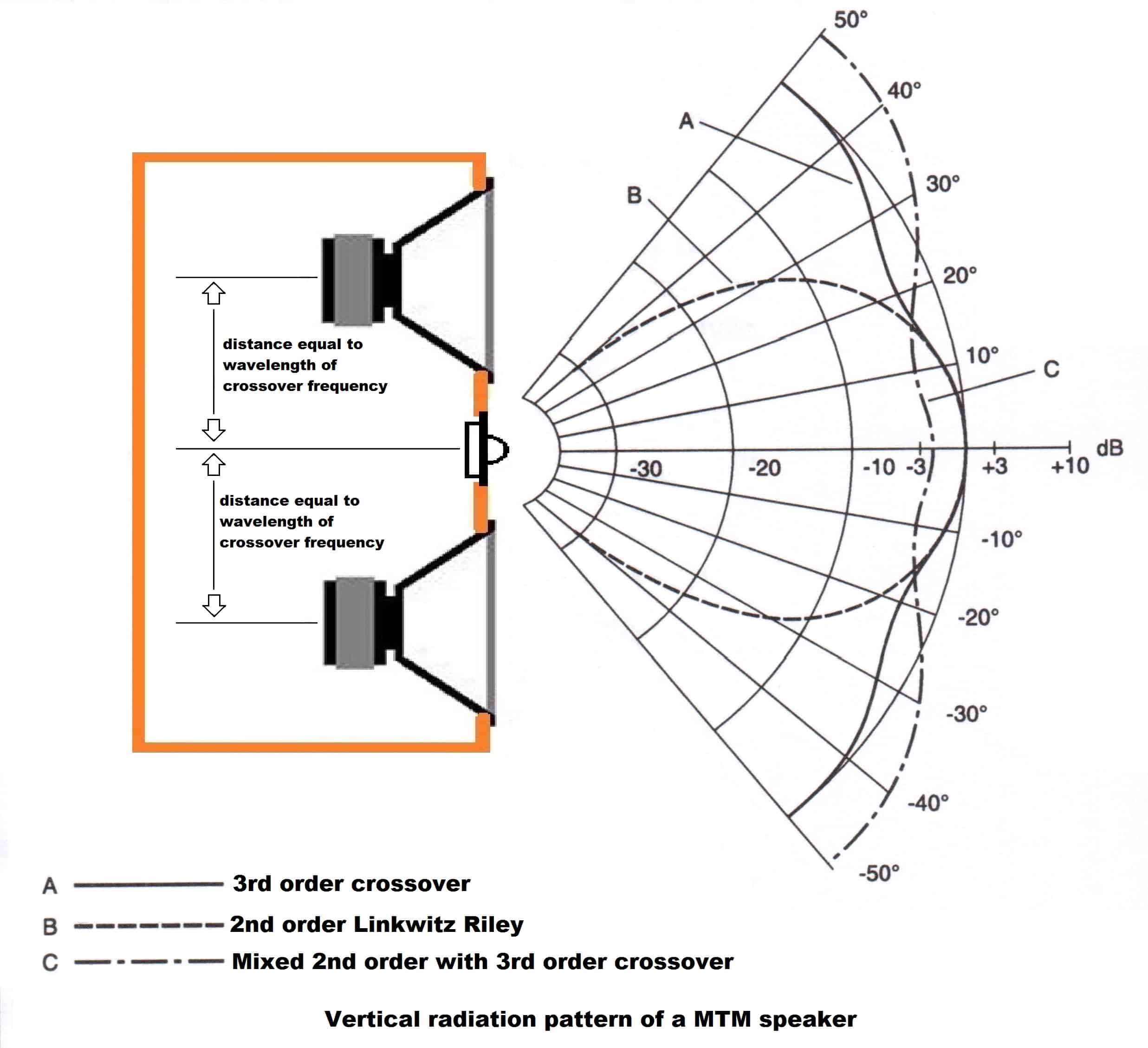
The MTM design needs the drivers to be spaced 1 wavelength of the crossover frequency apart, and use a 3rd order crossover topology. However, practice shows that the MTM speaker design produces a symmetrical acoustical radiation pattern no matter the type of crossover it’s using.
- A – classic 3rd order crossover.
- B – 2nd order crossover produces a large symmetrical lobe. This type of radiation pattern is useful when you deliberately don’t want much off-axis response, hence less room reflections.
- C – Combines a 3rd order high pass filter for the tweeter with a 2nd order low pass filter for the mid-bass. Radiation patter similar to normal 3rd order crossover.
The MTM speaker design is very popular specifically for its special acoustical radiation properties.
Conclusion
When designing a speaker system, the off-axis response is quite relevant, and especially important for some. For this reason, choosing the right speaker size, how you position them and the crossover topology you pick, will dictate the speaker lobing characteristics. Keep this in mind if you are meticulous about your audio projects.
References
-
- Speaker Building 201: A Comprehensive Course in Speaker Design by Ray Alden (Audio Amateur Pubns, 2004).
- Image source : link.
You May also Like


Learn loudspeaker design from scratch

23 comments
Hi,
Could you please get me the link to the polar response software?
regards,
seb
In this article I used some random plots that I found, just to serve as an example. To make a polar plot you need to take a lot of measurements for the various angles. To do this you have to move the microphone for each measurement, or if you own a turntable, you can place the speaker on the turntable and pivot the table to achieve different angles. As for software you can use SoundEasy.
Thanks a lot. I’m looking for a software for airflow simulations, like the picture of your post, with the driver and the port.
regards,
seb
A bit confused. There are no driver + port pictures. Maybe bass driver + tweeter. Anyway, I don’t think you can make polar response simulations with soundeasy (I’m not sure on that though). You can, however, measure the polar response.
I don’t know what you mean by airflow simulations. If you are referring to air port velocity, than you can easily do that with soundeasy.
test comment !
I’m talking about this one:
https://drive.google.com/open?id=0B668qFlw8VB-MjJXVC05aF9MMGs
regards,
seb
A real eye opening article. In particular, driver spacing connected to XO stuff and how XO slopes can tilt directivity
A. I’ve always thought a driver would beam any frequency w/a wave length shorter than its effective* size*. For example a 6″* would beam above 2.2Khz, a 1″ dome would beam above 10Khz.
B. Also my tri-amped towers’ mids (6″) & tweets (1″) centers are 4″ apart. I XO’d them @ ~2Khz**, 4th order high & low pass. Your thoughts on frequency & XO slopes?
** see A
Thnx, Tony
At the crossover region the responses of the 2 drivers overlap. So it’s only fair that the directivity is affected also.
Directivity is mostly important in outdoor applications. However, some people like to have speakers with very poor off-axis response. In this case, room reflections are no longer an issue. But this is usually achieved with complicated open baffle designs and horns.
Nevertheless, you shouldn’t get too hung up on this. Can’t really tell much from driver size and crossover point. If you are interested in the directional pattern of your sound system, you can always measure it. That’s the only way to accurately draw a conclusion.
You wrote:
“Above we have a vertical radiation pattern of a typical 2 way system with 3rd order crossover. The crossover frequency is 3000 Hz,…”
Did the builder choose to XO @ 3Khz? (Tweeter protection) Or… [you followed the above with]
“…so the distance between the 2 speaker centers is 11.4 cm (~about4.4″) wavelength of 3 kHz.”
This seem to suggest the drivers’ center-to-center spacing dictated a 3Khz XO frequency, not what the tweeter can handle smoke-free.
Though mine are 10.2 cm apart, I XO’d mine @ 2Khz to reduce/eliminate beaming from the (15.25 cm) mid.
They came XO’d (passive) @ 2.7K 2nd order. So far the tweeter handles the 4th order slopes w/out distress
Thnx, Tony
I think you confused things a bit. The crossover point value is purely random and it’s just to serve as an example. The spacing between drivers is then calculated after knowing the crossover frequency. The fact that they are spaced 1 wavelength apart is not some rule that you have to follow (in fact, you probably shouldn’t). However, if used this way, you will end up with that predictable radiation pattern. Doing the same for the 3rd order filter, we can compare the plots between them, and see the effects of the crossover slopes on the radiation pattern.
The fact that you have the distance between the drivers lower than the wavelength of the crossover frequency is a good thing because you will reduce phase issues that might occur. If you are not using the MTM setup with a 3rd order xover, lobing will occur no matter how you space your drivers. So don’t stress too much on this.
Great article, thank you for share with us.
You did wrote some article about time alignment?
Kind regards.
Norberto
Maybe these will help you out :
https://audiojudgement.com/audison-bit-ten-tuning-time-alignment/
https://audiojudgement.com/speaker-acoustic-center/
I attempted to us the formula you showed in the example even. I never get the answer you display, even if I use your example = f = 2 * 343 / 3.14 * 0.1316 = 1660 Hz
Try punching it in your own calculator. I think something is off in the formula. I get: 28.75…
28.75 doesn’t equal 1660
Hmmm….
It’s multiplications first and then the division. I added parenthesizes to avoid confusion.
Thank you for your information.
Could you explan the meaning of speacker effective diameter.
I confuse that means the diameter of frame or the one of cone or another.
If you look in the T/S parameters list of the speaker you will find one named Sd. That is the effective area of the speaker. From here you can calculate the effective diameter. If not, you can measure from the middle of the surround on one side to the middle of the surround on the other side. That is the effective diameter of the cone. The whole cone + half of surround.
Hey Marius,
Thanks for your content, they are of great quality and understandable. I’m following 3 of your courses and they are excellent.
Does the MTM 3rd order work with Butterworth and Bessel or does it have to be a specific topology? I’m looking at a center build with vertical MTM for better horizontal dispersion, but vertical is also a concern since the tweeter center will be about 12 inches below ears level. Don’t wanna end un between 2 lobes…
Hello! In theory, to have that uniform vertical dispersion you need to have a 3rd order filter on at least one crossover branch (either tweeter or woofer) and the other branch needs to be 2nd order or 3rd order. So, either both 3rd order or one 3rd order and the other 2nd order.
This is amazing information! Do lobing results assume that the acoustic centers of the drivers are time-aligned (via dsp) or positioned in a way that they are the same distance from the observation point? The image of the typical 2 way system with 3rd order crossover shows a downward angle of -10 degrees… is this a result of the acoustical offset of the drivers (tweeter is much further forward), or because of the crossover config? Thanks!
Hi,
I’m working with a specific type of full range driver, and I actually want to put two of that same kind in my speaker, to have less effort applied to each, as each would be dealing with only part of the range. So basically one is going to take care of the low freqs part, and the other the mids and trebs.
So my question is :
How about if the crossover point frequency is way longer (say lower mids, around 400-500hz) than the distance between driver centers ?
How will this influence the sound ?
I saw some dudes on the DIY Audio forum (some of them well versed in the exercise of speaker building) that this could actually be ideal.
What is your take ?
Hello! First of all, I would go for a mid-bass driver and a tweeter, rather than 2 full-range drivers. Secondly, I would argue that it’s better to keep them as close as possible. However, the wavelength at 400 Hz is pretty long, so it would be hard to spread them apart that much anyway.
Hi Marcus,
I get your point about a mid bass and a tweeter in a normal config, but the reason I am using two same drivers is because I like the sound of that driver from bottom to top, so I wanna keep that same driver sound coherence.
my question was really about if these two drivers on the baffle are say just 3 cm appart from each other, but being crossed at say 500hz, how is this going to influence sound response with regards to lobbing and such ?
Thanks a lot and keep the go work going guys !
Regards
Hello,
What kind of lobing pattern will two full-range drivers with no crossover and kept one next to each other exhibit? Both will be playing the same content and will occupy same air volume of the enclosure?
Thanks!