
4th order bandpass calculator – With box design example
How to build a 4th order bandpass subwoofer box in 7 steps?
The 4th order bandpass box design is not recommended for the first time builder. You need some experience before you get into these complicated designs. Actually, if you are a good listener and/or are savvy with enclosure design software, you shouldn’t have much of a hassle when making this kind of project. The problem is, even if you conceive a good 4th order bandpass design, but have slight building errors, the result will be sub-par. Now that you are all encouraged, let’s learn more about these bandpass enclosures.
What is a 4th order bandpass box ?
The term bandpass is also used in passive crossovers. Usually used for midrange drivers, to filter low frequencies and high frequencies at the same time, only to let the frequencies between the crossover points pass. How is this passive filter example relevant to the bandpass speaker enclosure ? It is, because when you look at the frequency response of a bandpass subwoofer, it looks exactly like the frequency 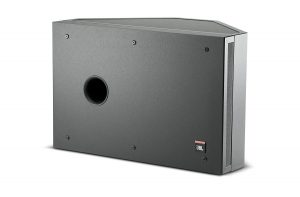 response of a speaker with a bandpass filter on it. Imagine the frequency response of sealed or bass reflex enclosure. For the very low frequencies, when the resonant frequency is reached, the response starts to roll-off. Now, for the higher frequencies, the response will naturally start to roll-off, at different points, depending on the speaker. Because of the size of the woofer, it will be impossible for it to play high frequencies at some point, so it naturally rolls-off.
However, the 4th order bandpass design acts differently. It is composed by two chambers : a rear sealed chamber and a front vented chamber. You can think of it like a normal closed box system, but the vented chamber in front of the speaker acts like an acoustic filter, a low pass filter to be more precise, so higher frequencies are filtered depending on how it is designed. Because of this filtering, the frequency response bandwidth is quite narrow. You can make it broader, but you will sacrifice efficiency. Or you can make it even more narrower and increase efficiency by a lot. This seems appealing for those who want to play a narrow frequency range at very high volumes (like car audio SPL competitions). Sealed and bass reflex can make this kind of trade-off also, but bandpass has a better “yield”.
How to make a bandpass box ?
Further on, I will explain how to design your box without any design software. Your pen and paper will be the actual 4th order bandpass calculator. This will get a bit technical, but I’m sure you will figure it out. Before you start off your project, you should first select a woofer. Anything that will work well in a sealed box, will work well in 4th order bandpass design as well. If you want to crunch numbers when choosing your speaker, you can divide fs / Qes , and the smaller the number, the better (lower than 60). This means a good bandpass speaker will have a low fs, or high Qes, or both.
First of all, let’s define some terms, so we can speak the same language :
- fB – Tuning frequency of the port in the vented chamber.
- R – The radius of the port in centimeters.
- Lv – Length of the port in centimeters.
- fL – f3 of the low frequency roll-off.
- fH – f3 of the high frequency roll-off.
- Qbp – Q of the sealed rear chamber.
- Vf – Volume of the front chamber (the acoustic filter chamber) in liters.
- Vr – Volume of the rear chamber (the sealed chamber) in liters.
- S – Passband ripple (How many ±db does the frequency response deviate from linear frequency response).
- Vt – Total volume (Vf+Vr) in liters.
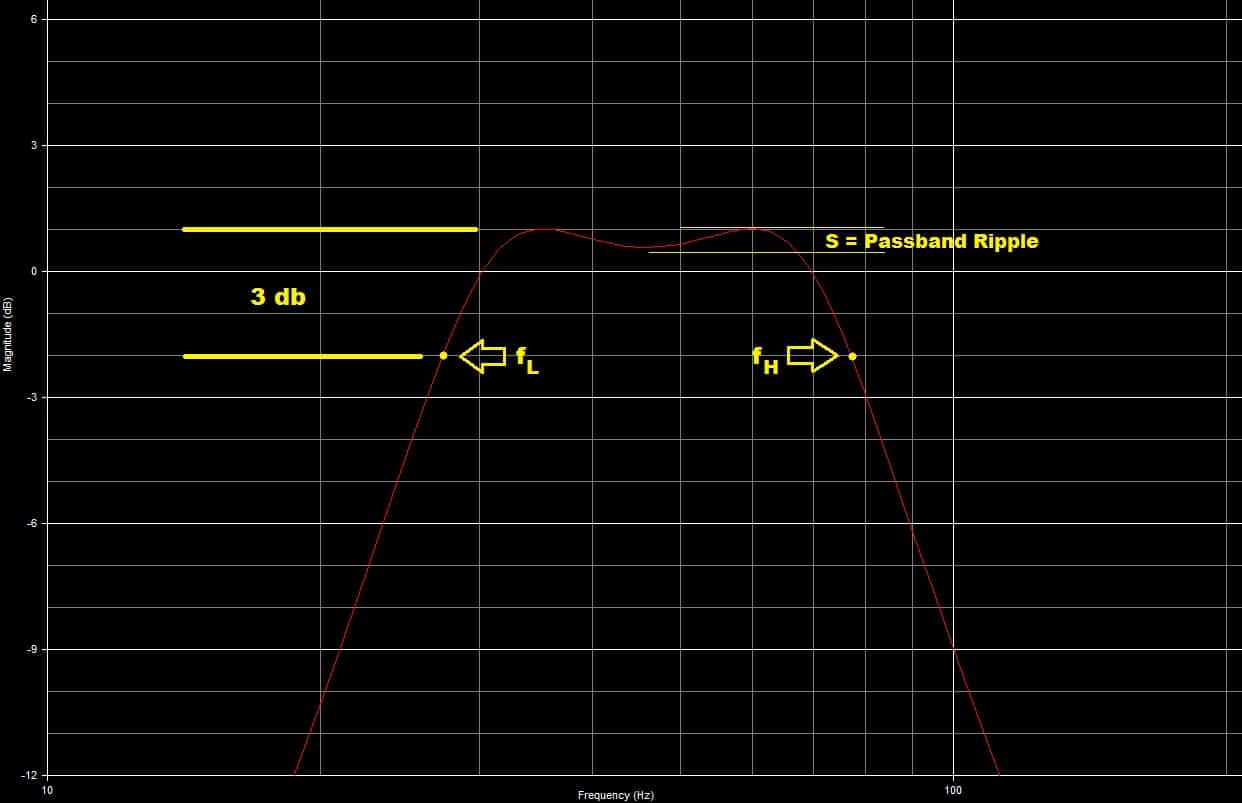
As you can see from the graph above, fL and fH are positioned -3 db after the response starts to roll-off (for low and high frequencies). The passband ripple measures the amount of variation from linear response. High amount of ripple will result in peaks / dips in the frequency response. Judging from our graph the ripple looks like around ±0.5 db.
4th order bandpass calculator in 7 steps
We are going to explain, step by step, what are you supposed to do in designing a great sounding box. To make things more clear, we are going to use a real life woofer, and design a bandpass subwoofer box for it. The woofer I chose is the JL 10TW3-D4 (Amazon affiliate link). There is no particular reason for my pick, other than it has good specs for a sealed enclosure, which means it will be good for bandpass as well.
How to design loudspeakers - video courses


I’m going to list the Thiele / Small parameters of the JL woofer for convenience :
- Fs = 32.3 Hz.
- Qes = 0.656 .
- Qms = 11.35.
- Vas = 19.82 L.
- Qts = 0.62.
- Xmax = 15.2 mm.
Step 1 : Know what do you want
You have to understand that there is no perfect bandpass enclosure for each kind of woofer. You have to make compromises between linear frequency response, how wide the frequency response is, and efficiency. General rule of thumb is that the louder it is, the narrower the frequency response is. Depending on what you want to achieve, you will have to find a balance between these 3 aspects, so that you will end up with a 4th order bandpass design that suits your needs.
Step 2 : Determine how linear the frequency response should be
Remember, at the beginning of the article, we talked about some parameters that are relevant to this project. One of them is S, which is the passband ripple. This ripple, describes how many ±db, the frequency response will digress from linear response. In a perfect world the ripple would be ±0 db, which is achievable. However, that is at the expense of the other 2 characteristics we need to take care of, in the later steps.
There are 3 values of S, which give an acceptable amount of ripple, and have the following characteristics :
- Best transients for S = 0.7, and 0 db ripple.
- S = 0.6 , somewhat degraded transients , ±0.35 db ripple.
- S = 0.5 , worse transients than S = 0.6 , ± 1.25 db ripple.
Picking a certain value for S, will narrow your possibilities for the other factors we need to figure out. Another guideline which is useful when choosing S, is that if you go for a bigger value (0.7), the frequency response will be narrower. On the other hand, a lower value S (0.5), would translate into a wider frequency response. So, choose the ripple you like, but keep this in mind when doing so.
Here is a table with the values of S, and the values of the frequency response and sensitivity, corresponding to that certain S value. Get familiar with this table, as we will need it for the next step as well.

- For our woofer we will choose S = 0.6.
Step 3 : Determine the desired frequency response bandwidth and sensitivity
Now you have to determine the values of fL and fH. This means you will determine the – 3 db points, when the response starts to roll-off, for both low frequency and high frequency roll-offs. This will effectively set your frequency response bandwidth between the two values. You figured out the value of S, at the 2nd step, now you will chose the values of fL and fH, corresponding to that S. After that, the value of the sensitivity is chosen for you. If you choose a certain value for the sensitivity, then the values of fL and fH are chosen for you. This is the balance I talked about, that you need to make, to find the sweet spot.
To find the values of fL and fH you have to do the following :
- fL = Fs / Qts * (fL factor)
- fH = Fs / Qts * (fH factor)
Now let’s do some number crunching for our woofer :
- I’m choosing the sensitivity to +5 db because I want a loud bandpass enclosure.
- This means that the start and end of the frequency response are chosen for me.
- fL = 32.3 / 0.62 * 0.7317 = 38 Hz.
- fH = 32.3 / 0.62 * 1.6877 = 88 Hz.
So, we have figured out that the frequency response will be from 38 Hz to 88 Hz, with a +5 db boost and ±0.35 db ripple.
Step 4 : Calculate the volume of the front enclosure
Calculate the front chamber volume using the following formula:
Vf = (2S * Qts)2 * Vas
- Vf = (2 * 0.6 * 0.62)2 * 19.82 = 11 L
Step 5 : Calculate the volume of the rear enclosure
Calculate the rear chamber volume using the following formula:
Vr = Vas / ((Qbp / Qts)2 – 1)
- Vr = 19.82 / ((1.1113 / 0.62)2 – 1) = 19.82 / (3.21 – 1) = 9 L
Step 6 : Calculate the tuning frequency of the front chamber
Calculate the tuning frequency using the following formula:
fb = Qbp * ( Fs / Qts)
- fb = 1.1113 * ( 32.3 / 0.62) = 1.1113 * 52.1 = 58 Hz
Step 7 : Calculate the dimensions of the port
The radius of the port (R), should be as large as possible, to minimize port non-linearity. Understand that making the port bigger, will mean that the length of the port will be longer. This means there are certain limitations to how large you can go.
- For our project I’m choosing a port radius of 5 cm (10 cm in diameter).
- R = 5 cm.
Calculate the port length using the following formula:
Lv = ((94250 * R2) / (fb2 * Vf)) – (1.595 * R)
- Lv = ((94250 * 52) / (582 * 11)) – (1.595 * 5) = (2356250 / 37004) – 7.98 = 63.68 – 7.98 = 55.7 cm
Results for our 4th order bandpass calculator
Now we have finished making a 4th order bandpass design box for our 10″ JL woofer, and the dimensions are as follows :
- Front chamber = 11 L.
- Rear chamber = 9 L.
- Port diameter = 10 cm.
- Port length = 55.7 cm.
Please bear in mind, that these are the net volumes. This means that you will have to add the volume displaced by the speaker, to the volume of the rear chamber. Also the volume displaced by the port needs to be added to the volume of the front chamber. Add any other elements to the total volume (like bracing).
How to design loudspeakers - video courses
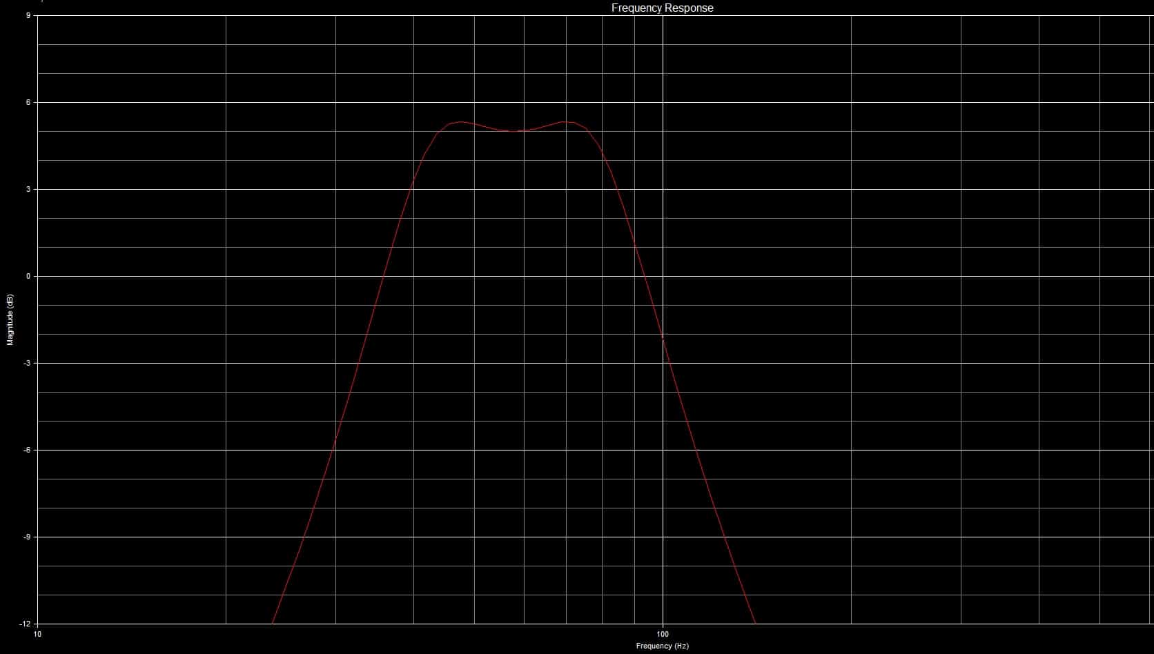
The frequency response will look like the following graph :
Variations of 4th order bandpass enclosure
In the example above, we used just one speaker, and made a 4th order bandpass design. If we use 2 speakers, we can place them in different positions so that we end up with different variations of bandpass enclosures. Here are some variations of the 4th order bandpass enclosure:
- Single driver bandpass subwoofer box.
- Dual driver push / pull bandpass enclosure.
- Push / pull compound bandpass box design.
- Triple chamber bandpass subwoofer box.
- Push / pull triple chamber bandpass box design.

For the dual driver push / pull variation, calculate the volume of the front and rear chamber, for each individual driver, and then add them up. For the triple chamber bandpass subwoofer box, the rear chambers are separated, and therefore calculate them normally. The 2 drivers are sharing the center chamber. So calculate the volume of the front chamber for each driver individually, and add them up, to get the volume of the center chamber. When there is a push / pull configuration, remember to connect one of the drivers out of phase electrically (reverse polarity).
Conclusion on bandpass box design
The 4th order bandpass box design is definitely an interesting solution. If you do not need a wide frequency response, and want a boost in output, you should seriously consider it. However, the enclosure can get quite big, and you don’t have direct access to the speaker. As a result, if you need to replace the speaker, you have to tore open the enclosure. The design and build difficulty can be a let down for the inexperienced builder, but if done properly, the 4th order bandpass design can be quite impressive.
References
- Loudspeaker Design Cookbook 7th Edition by Vance Dickason (Audio Amateur Pubns, 2005). (Amazon affiliate link)
- Introduction to Loudspeaker Design: Second Edition by John L. Murphy (True Audio, 2014). (Amazon affiliate link)
- Image source : link.
You May also Like


Learn loudspeaker design from scratch

212 comments
Nice write up
Thank you for breaking this down in easy to follow directions. I have always wanted to know how they were figured. Thanks to you, I will be building my first one today to enclose a JL Audio 13.5 shallow mount ironically enough. Thank you again!
prejudice compliments for the explanation. very clear the only past that I do not understand is this f L = F s / Q ts * (f L Factor)
f H = F s / Q tof H factor fl and fh factor have fixed values or has taken them from the woofer parameters. I have an audio jl 12w7
The values of fL Factor and fH Factor can be found in the alignments table, which can be found at step 2. Qts and Fs are woofer parameters and can be found in your 12W7 parameter spread sheet.
Let’s say you choose the ripple S=6 and the sensitivity of +3 dB. Then, the fL=0.6217 and fH=1.5778. You have the liberty to choose other values for fL and fH (from the alignments table), but then the sensitivity will be different.
Grazie mille per la spiegazione
these are the characteristics of my driver. S factor which I could use to have a good system
FS 27,2
Qes 0,514
Sgq 7,807
Qts 0,482
Vas 66,0 lt
Xmax 29mm
No 0,25%
(1w/1m) 86,2 db spl
Sd 0,0542 mq
That is a choice that you have to make, there is no perfect choice, it depends on your application. I would go for a +3 dB sensitivity and when you choose S, consider the following :
lower value S means : higher ripple, wider frequency bandwidth, worse transients, smaller box
higher value S means : low or no ripple, narrow frequency bandwidth, better transients, bigger box.
If you have a hard time choosing you can go for S=0.6 which is the middle point.
This is great stuff . Thank you for providing the formula so its possible to see the way parameters influence each other
I am always enlightened when people quote texts that they have drawn information or inspiration from , it so helps for complete understanding .
Bravo
Grazie ancora
from the calculations I got back chamber volume 20.483 liters 22.080 liters anterior chamber diameter pipe length 10cm led 1901.420 cm. Now as I understand it should add to the rear volume the volume occupied by the driver, and front volume that occupied by the conduit?
The volumes are correct. The pipe is 10 cm in diameter and 38.7 cm in length. And yes, those are net volumes. You have to add the volumes displaced by anything (driver, pipe, bracing etc)
The length I 19 not 38. But if I put a tube with blunt ends I have to calculate as if it all straight?
I have made the calculation again, and even used a modeling software and it’s 38 cm. Check your calculations. If by blunt you mean flared, then the total length (38 cm) is the length of the straight pipe + half of the length of the flare.
Ho eseguito la formula sopra riportata. Quindi 38 cm da metá svasatura interna a metá svasatura esterna? Scusa tutte queste domande ma non vorrei fare dei danni
Corretta 🙂
La formula che ho eseguito è questa L v = ((94250 * R 2 ) / (f b 2 * V f )) – (1.595 * R)
E quindi L v = ((94250 * 25) / (3123,580* 22,080)) – (1.595 * 5)=26,189
La Fb=55,889
Vf=22,080
Yes, you are right. I somehow used the Qbp from S=0.7 and got an Fb of 47.9. But, taking a closer look now, you are correct. The length is 26 cm
Is there some preferenced distance between the speaker and the port? The configuration of the two (on the same side of the box, on in one side and one in the other, ecc..) is going to change some parameter of the system??
All things being equal, port placement shouldn’t affect functionality. You just have to take into consideration that the back end of the port (the one which is inside the box) should be a certain distance from the nearest panel. This distance must be equal or greater to the diameter of the port.
help please , I can’t count the chamber and port , I don’t understand the subwoofer machete M15 D2 here the data of Thiele small SPL – 88.28 dB. vas-75.36 L. FS-34.10 Hz . BL-16.70 qts-0.63. I love when low bass.
For S=0.6 and a sensitivity of +4 dB you get the following :
Rear sealed chamber : 42.5 L
Front vented chamber : 43 L
Port diameter : 150 mm
Port length : 300 mm
For S=0.7 and a sensitivity of +3 dB (this will go very low, but the enclosure is big) :
Rear sealed chamber : 92.4 L
Front vented chamber : 58.6 L
Port diameter : 150 mm
Port length : 350 mm
thank you very much for your help !
Un’ultima domanda per determinare la lunghezza del condotto devo tener conto del diametro interno effettivo o di quello esterno perché internamente misura 9,6 cm ed esternamente 10 cm. Mille grazie
the internal diameter
Ok grazie mille proverò a realizzare questo progetto e ti farò sapere grazie ancora
Buongiorno! Volevo Avere un consiglio per la Realizzazione del box mio passa banda avrei Pensato di Mettere Sulla parte anteriore per Poter VEDERE il conducente del plexiglass vorrei Sapere di che spessore?Le altre Pareti Sono in MDF da 30 mm
Please stop speaking in Italian. I never used plexiglass before, so I can’t tell you how thick it should be. However 30 mm MDF is really thick. Totally overkill in my opinion. Don’t get me wrong, the thicker the better. But the enclosure will be very heavy. Most definitely you won’t be able to lift it alone.
Buon giorno! Volevo avere un consiglio per la realizzazione del mio box passa banda avrei pensato di mettere sulla parte anteriore per poter vedere il driver del plexiglass vorrei sapere di che spessore le pareti sono in MDF da 30 mm
I try with plywood 28 mm.
I am building a fourth order bandpass enclosure for 412 inch subwoofers and I am wondering if I will be able to do this with a space that is 36 x 37 x 15 please get back to me with answer or if you may even have a Nother suggestion if I could do a six order Banpass enclosure with 3 12s instead in that space
That’s a really big box. Calculate the volume for 1 speaker and multiply that by how many speakers you have. That’s your overall volume. My guess, it will surely work for 3 speaker, but you have to check for 4.
I have these factors:
Fs 30
Qes 0.53
Qms 7.07
Vas 67.8
Qts 0.49
Xmax 10
And with S:0.6 and -2dB i got Lv < 0, could you help me with that or am i doing something wrong
fL = 30 / 0.49 * 0.4052 = 24.8 Hz
fH = 30 / 0.49 * 1.3612 = 83.3 Hz
Vf = (2 * 0.6 * 0.49)^2 * 67.8 = 0.34 * 67.8 = 23.05 L
Vr = 67.8 / ((0.7427 / 0.49)^2 – 1) = 67.8 / (2.29 – 1) = 67.8 / 1.29 = 52.55 L
fb = 0.7427 * (30 / 0.49) = 45.5 Hz
I suspect you have a 12″ woofer so a 15 cm diameter port would be nice. R= 15 / 2 = 7.5 cm
Lv = ((94250 * 56.25) / (2070.25 * 23.05)) – (1.595 * 7.5) = 5301562.5 / 47719.26 – 11.96 = 111.1 – 11.96 = 99.14 cm
That’s going to be pretty hard to implement. Let’s try with a 10 cm diameter port R = 5 cm
Lv = ((94250 * 25) / (2070.25 * 23.05)) – (1.595*5) = 2356250 / 47719.26 – 7.97 = 49.37 – 7.97 = 41.4 cm
Good luck!
The numbers that I came up leave my Vf more then half as small as my Vr. Most 4th I see the sealed cabinet is smaller then the ported cabinet. I was wondering if I’m doing this right. Looking for a very flat response for sound quality for home stereo.
S=0.5 0db
Fs=33
Vas=1.39
Xmax=8.128mm
Qes =1.058
Qts=0.825
Qms=3.751
83.3db
Your driver has a very high Qts and it’s not the most fortunate pick for BP4. If you use S=0.7 you will see that you will get negative numbers which indicate that the alignment is not possible for your driver.
Bună seara, și felicitări din nou pentru toate marile sfaturile pe care le dau noi, cititorilor. pentru că am de gând să realizeze a patra comanda mea și a vrut să știe cum să calculeze volumul tubului reflex pentru a putea adăuga la volumul caseta. și conducta de formă circulară
Thank you for this write up! You’ve made it very easy to understand banpass box design
hi.can i ask u a question?
i got a sub with these parameters
Fs 43
Qes 0.5
Qms 5.3
Vas 12.15
Qts 0.46
Xmax 22mm
i want to use 12th of this sub in a 6th order box if u can please help me.
thank you
There isn’t much documentation out there for 6th order bandpass. Bose has a patent on the design and unfortunately it’s not available. You can find software to model the 6th order bandpass response, and you could make one for personal use, without any legal issues. However, the design has a very thin tolerance for error, and since you are vaguely asking for help, I’m advising you to chose another enclosure design.
hello
what’s you suggestion about regarding ti subwoofer parameters?
what’s you idea about 4th order
please advise us one technically channel virtual network and website or Email or another connection way.
best regards
Hi!
I’m calculating a 4th Bandpass Triple Chamber for Dayton Audio RSS210HF. I’m calculating a single woofer first to add the Vf values later. But I have some questions regarding the ports…
I want the frequency range to be really low, as the mid range is taken care of by other speakers. The woofers are supposedly able to handle the low frequencies quite alright. Low sensitivity is not going to be an issue, as the amp powering them will provide more than enough, so I went for 0,35dB ripple and -3dB sensitivity to get the frequency range where I want it, Fl 19,2 Hz & Fh 69 Hz.
However, I’m confused by the port. Using a 6 inch port will give a length of 340 (!) centimetres, and a 4 inch port will give a length of 148 cm, which isn’t possible to fit.
Also, how do I calculate more ports since I’m building a triple chamber with twice the volume of the front chamber Vf? I assume that two equal 4″ or 6″ ports won’t result in the same Vf as a single one?
Vf 11 litres
Vr 42,3 litres
Fb 37Hz
Lv 340cm/148cm ????
Link to woofer… http://www.daytonaudio.com/index.php/rss210hf-4-8-reference-hf-subwoofer-4-ohm.html)
Specs
Fs 29,6
Qts 0,57
Qes 0,69
Qms 3,25
VAS 23,71
Thanks
Looks like you already calculated the front and rear chamber volumes. In a triple chamber, the rear volume is the same (each speaker with its own chamber). And the front chamber is shared by the 2 drivers, and it has to be double the volume of Vf.
Unfortunately you calculated the port correctly. You can’t do nothing about that. The problem is that the Vf is only 11 liters. As the volume of the ported chamber get’s larger, it will demand a shorter port. Only thing you can do is go for a smaller diameter port. Going for 2 ports is not a solution. For ex : If 1 port of 4″ diameter needs to be 148 cm long, 2 ports of 4″ need to 300 cm EACH. So you can understand that makes things even worse.
Try to choose another alignment, where the ported box is bigger, or go for a smaller port (but you risk unwanted wind noise).
Hello,
I want to build band-pass enclosure as specified above with RCF L15S800 and i calculated Vf= 16,6 L which is 0.016 m3 and Vp=10,2 L which is 0.01 m3. I wonder isnt this a bit too little volume for 15″ transducer ?
I wait for Your help…
Your calculations look correct. Your driver has a very high Fs for a 15″ woofer. Very high sensitivity also. It’s probably designed for outdoor use, to be very loud. Because of this, it doesn’t go very deep in bass. Since it’s not playing the very low notes, it doesn’t demand a big enclosure.
Thanks a lot Marius 🙂
I’m obviously really thick as I don’t get any of that!
Is there anyone here can help me design a 4th order box as I don’t have a scoobie what any of those calculations mean??
thanks
can someone help me what a three chamber for 2 8″ kicker C8 old school model.
I have a Rockford fosgate 12″t2. With a fosgate 1200rd amp, rms 1347 watts @ 1ohm. Would a 4th order box rock my Toyota t100?
Yes it would :). Probably you should go for bass reflex though. You have enough power and it’s easier to make.
Any secrets of the bass reflex or a helpful site?
Check out these 2 articles :
https://audiojudgement.com/bass-reflex-speaker-design/
https://audiojudgement.com/bass-reflex-alignments-explained/
I will read them! Thank you ! God Bless you.
Maybe one of you could help me out:
I am trying to design a small(ish) sub to fit under the sofa. In order to see what woofer could fit the bill, I have been trying a couple different ones.
With a Monacor SP-202PA (Q_ts= 1.1; V_as= 12 L; Q_es = 2.25, f_s= 68) I am getting a usable design even with S=0.7.
The problem is that I am getting a negative rear volume.
V_r = V_as /( (Q_bp/Q_ts)^2 )-1
V_r = V_as/ ( (0.8489/1.1)^2 )-1
Q_bp/Q_as is smaller than 1, so its square must also be. Subtract 1 and you end up with a negative coefficent to scale V_as.
I’m missing something very obviuos, ain’t I?
Your driver has a Qts of 1.1 which is very high. It is suitable for infinite baffle, and not much else. If you want a small enclosure you should take a look at sealed enclosures. You should definitely forget band pass.
Yeah, you’re probably right.
The damping on that particular chassis is terrible. The other ones that gave negative volumes are also very non-compliant drivers, so the math is obviously teeling me to keep my hands off cheap rubbish like that. :o)
How do you choose the S value?
I dont quite understand that.
A higher S number will translate into better transient response and better linearity. However, the response bandwidth will be narrower. (and vice-versa)
The PS48 subwoofer of bose (bass module from a Lifestyle V35 for exemple) comprises 3 event on the from face. With type of isobaric construction is it exactely ?
Because there is a small cavity inside the subwoofer box where the 2 speaker are mounted, but the cavity is not completely closed.
The box also presents two other opening, one on the upper part of the box (seems to be attached to the upper speaker) and a second at the lower part of the box (seems to be attached to the second speaker). What is the utility and functionning of all theses 3 openings ?
Thanks for explanations.
Can’t really tell for sure from pictures. But my guess it’s a 6th order bandpass enclosure (because bose has the patent on the design) and the extra cavity on the inside is an isobaric setup to reduce the volume of the box.
Thanks a lot for your reply.
On an isobaric construction the internal cavity is generally totally closed. But this is not the case here with the ps48 sub.
Do you know the reason ?
Do you think is it possible to design a sub similar to a PS48 from BOSE perfectely adapted to Home Theater use ?
Note that the particularity of this “bass-medium” enclosure from bose, it to work upto 260 hz ! (On the upper part of bandpass).
If you say that the inside cavity is open it does rise a lot of questions for me too. You kinda expect this from bose. This is their philosophy : very cheap speakers, but over-engineered enclosures and a lot of digital processing. If you try to copy the design, not knowing how it works, you will most likely end up with something that you won’t be proud about. The fact that it goes so high in frequency response means one of 2 things : the lower part of bandpass is high as well (not hitting the very low notes) or it does go low in frequency but has poor efficiency rating (not impressive in volume department).
I need some help. I can’t figure out the Qbp of my woofer. It’s a DDX-15D2. I have my front enclosure volume as 13.308L
I cannot tell you that. Qbp doesn’t depend on the speaker. It depends on how linear you want the frequency response (S), frequency response bandwidth (fH and fL), and efficiency of the enclosure. These are parameters that you choose (more or less) however you want. Read the article again and pay more attention.
So when designing the triple chamber how does port size work? Do we just double it in size as we do the volume of the box?
No. You just double the volume of the chamber (so Vf is now double). Set a diameter for the port as you would normally (go for a larger diameter now so you don’t end up with chuffing noise). Then, calculate the length of the port using the Lv equation (difference is now that Vf is larger so the length will be different).
I want to do a double 18” fourth order bandpass. I want both drivers to share the rear chamber in parallel. What do I do for calculating Vf and Vr?
I would like both magnets housed in the sealed chamber
It’s just like having one speaker but with double the Vas value. The rest of the parameters (which are relevant to this enclosure) remain the same (Fs, Qts).
Hi, I have TWO of these subwoofers going into a 4th order bandpass box, both magnets in the ported side with their own separate sealed enclosures. I am looking at around 1.2 cubic feet per sealed chamber, and around 5.5 cubic feet on the ported side. My enclosure should be around 32″ wide, 30″ long, and 14″ tall. Using these specs, I am trying to figure out the port size for this. I will be building a rectangle shaped port, but not sure how big to build it. I want a musical box and don’t mind losing some output in exchange. Any ideas on port size and length? Hoping for about an 8-10″ port, not sure how long to go though.
Woofer Size 10″
F(s) 37.68 Hz
R(e) 7.06 Ohms
Q(ms) 5.231
Q(es) 0.536
Q(ts) 0.486
V(as) 9.340 liters (0.330^ft)
L(e) 8.74 mH
M(ms) 282.10 grams
C(ms) 0.09 mm/N
Sensitivity 81.59 1W/1m
BL 29.67
RMS Power 1200W
Peak Power 2400W
Displacement .07^ft”
Replying to my own comment, it looks like if I go an inch taller, to 15″, it gives me a 1.25 cubic foot sealed area per side if I go 9″ deep. That gives me a 5.5 cubic foot ported area at right around 20″ deep. If I did my math correctly, a 10″ wide by 8″ tall rectangle port should be 9.45″ long to be tuned at 48Hz. It seems like everyone says that’s a happy medium tuning area for a musical box. Any comments, questions, concerns would be greatly appreciated.
Sealed area: 32″ wide X 15″ tall X 9″ deep for 2.5 cubic feet giving me 1.25 cubic feet per chamber.
Ported area: 32″ wide X 15″ tall X 20″ deep for 5.56 cubic feet
Port size: 10″ wide X 8″ tall X 9.5″ long for 48Hz tuning
First of all, those dimensions that you quoted will guarantee you a misaligned enclosure, that will sound awful. Secondly, I would advise you to choose an easier to make enclosure. Bandpass enclosures are difficult to design and to make. And have all sorts of inconveniences (like if you want to take the speaker out, you have to destroy the box). I’m not saying you should not try to make a bandpass enclosure, but you seem to not have much experience. As a result, I invite you to look at sealed or bass reflex enclosures.
I have zero experience in building a 4th order bandpass box, but have lots of experience building sealed and ported. That’s why I’m asking all the questions, I don’t want another sealed or ported enclosure.
So working on designing a 4th order for my side by side and have some questions. I was playing with 2 Rockford p2 12s as I’m not sure exactly what I’m going to run but something around that. They have qts of .54, fs of 27.2, and vas of 81.5 liters.I did an s value of .6 with a +3db output. The problem I run into is then I get 2.4cuft for the front chamber(before any displacement) and 2cuft for the rear(before displacement). One this seems really small, I have 11 cubes I can use, and two isn’t the ratio supposed to be 2:1 or 3:1? These are the formulas I used
I actually did the calculations myself with the numbers that you mentioned. I got Vf = 2.41 cuft , Vr = 2.43 cuft, tuned at 50 Hz. Frequency range 31 – 80 Hz, +3 dB efficiency. There is no rule like this chamber should be this size compared to the other. These calculations reflect the 4th order bandpass alignments. You can make the box whatever volume you want, but you will need a box modelling software to see if the frequency response will suit you. 5 cubic feet box is not a small box in my standards. Going for a larger volume will make it louder but reduce the frequency response bandwidth. If you really want to use all of the available space, my advice is to go for bass relfex. Less things that can go wrong.
hi there – and thanks for a informative site.
At the moment I’m working on a 4th order bandpass woofer for my home cinema. I want the freq. range to be say 20-70 Hz. It’s gonna be a flat formation 300 mm in hight inside and 1000 mm in width, but I still want a 15″ speaker. And there’s gonna be two 6″ ports. The woofer is going to be a podium for the 2nd row of seatings. I want it so make an ‘atmosferic’ sub, in order to feel the helicoper noice etc.
But it seems very difficult to get any decent 15″‘er with Fs/Qes that goes below 60, or even 100.
So any suggestions of a good speaker, or is that 60 value different with a 15″ speaker?
Thanks and all the best
Óla Jákup
I don’t understand why you are having such a hard time finding a 15″ woofer that will go that low. Usually they have a low resonant frequency. My guess is that you are looking at pro audio drivers, which have a higher Fs, but high power handling. Check out normal hi fi drivers.
how would this convert to a triple chamber design
trying for skar sdr-12 D4(i know but they are payed for)
fs 32hz
qts0.5
vas 43.3
hoping for s 0.7 0db to +3db depends on space
ok i finished the page and answered my question
ok going with a radius of 10 cm which is 20cm round,which would be 7.874 inch i get 24.54cm long which is 9.66inch ,how can i slot port this?
Make a slot port with the same area of the circular port. PI * R^2 = 3.14 * 10^2 = 314 cm2 (for example 35 x 9 will result this area). And the length is exactly the same as the circular port.
I’m looking for a total 4 ohm load, which driver would work better in a 4th order enclosure, one of these?
https://www.parts-express.com/dayton-audio-um8-22-8-ultimax-dvc-subwoofer-2-ohms-per-coil–295-508
or two of these face-to-face in an isobaric arangement?
https://www.parts-express.com/dayton-audio-rss210hf-4-8-reference-hf-subwoofer-4-ohm–295-456
Well, the 2nd option is either 2 ohm or 8 ohm, since you have two 4 ohm drivers. The first driver (Ultimax) seems like a good choice anyway.
I think I maybe linked to one of the wrong drivers.
However, How about if either one was edequately powered, would two of the RSS210hf drivers in an isobaric 4th order bandpass arangement work better or worse than 1 um8-22-8 ultimax in a single driver 4th order enclosure?
The whole point of going isobaric is to cut the enclosure size in half. However, you have to make room for an additional driver. Also, a smaller enclosure demands a longer port to keep the same resonant frequency. If you add all of these up, you don’t get much of a volume benefit, while paying for an additional driver. Isobaric is nice for very specific applications. Haven’t made any number crunching but my guess would be that it’s not worth it. Go for the single ultimax.
You are right, I gain a tiny bit of power handling having two drivers, the increased cost of the additional drivers, and the absolute inability of being able to fit the port inside for the desired Fb. if the port goes outside then it looks like a submarine. The enclosure volume actually becomes so small that two drivers won’t fit face-to-face.
I NEED HELP,MASSIVE AUDIO,TOROX 124 I HAVE CAME UP WITH 3 DIFFRENT FIGURES AND I DONT KNOW WHY.S.7 0DB. FS 36.4 QES .67 QMS 4.2 VAS 23.5 QTS .57 3 CHAMBER BOX. I HAVE 1.05 FRONT 1.44 REAR,AND THIS PORT I HAVE A -4.ORR IS IT FRONT 1.5 REAR .695 4 INCH PORT 12.20 IN LONG ALL CUBIC FOOT PLEASE LET ME KNOW.bethington@gmail.com
For a +3 dB box with S7, I got 0.73 cu ft front, 1.37 cu ft rear chamber. Tuning frequency 46 Hz. 4″ diameter port of 8.4″ in length.
is that front shared by both or individual? im going for 3 chamber and that doesn’t leave much room for the port. im not questioning your ability im just making sure i get it right
Ah, I thought you had a single speaker. Good thing you asked. In that case, each speaker has its own sealed cabinet of 0.73 cu ft and the ported enclosure has to have 2.74 cu ft of volume. Since you have 2 speakers, go for a 6″ diameter port, of 8.42″ in length. Remember, the quoted volumes are net volumes. You need to add everything that takes up space (volume displaced by speaker, by port, braces etc).
Thanks for the information you rock.
How would one go to work if you want to do 8×15 in a 4th ?? 4 on the left and 4 on the right with ported chamber in the middle all inverted to the ported chamber . Each sealed section would be around 15cm x 90cm x 105cm = 2.5cft and the ported chamber will be 60cm x 90cm x 105cm = 15.6cft can always do away with ported and add 1.2cft to sealed??
You probably want to do hair tricks and stuff. So, sound quality is not important. Just use all of your available space. You forgot to mention port size, but any window-like opening will do.
anyone have a design for a skar evl 18 4th order that can go into a quad cab truck with the seats removed all this qts and S stuff is beyond mw i juat need some dimensions or plans and i can build it the technical stuff is beyond my comprehension
I’d like to build a 4th order box and have a small single 10” sub with a (FS 30.4, Qts .55, Qes .64, Qms 4.22, Vas 1.34 ft3 ) just trying to hook my son up with a great sounding box . I had a 3 chamber as a youngster and it pounded any help is appreciated.
OK. Here are some numbers : Rear chamber : 0.67 ft3 , Front chamber 0.79 ft3. The front chamber is tuned at 52 Hz, so this means you can go for a 3″ diameter port and 6″ long, or a 4″ diameter port and 11.7″ long. If you have the available space the bigger port will have less air turbulence. The volumes are net volumes and do not include the volume displaced by the speaker, port, braces etc (you have to add them up).
Thanks for the info I appreciate it?
Hi i want to make a 4th order bandpass (triple chamber) box with two rockford p3d4-12. with
Fs:27.7 hz
Vas:57.7 l
Qts:0.52
Qes:0.57
Qms:5.60
can you help me please?. I want the box from 33hz to 80hz. i do all the math but at the end on the port length i got a massive number.
Tank you
Sealed chamber 69 liters. Ported chamber 60 liters, tuned to 45 Hz. Port diameter 150 mm (5″) and length of 320 mm. Response from 30 Hz to 68 Hz.
Skar Audio ZVX-8 D2 – 8″ SPL Car Subwoofer
Dual 4 Ohm Voice Coil Configuration
Peak Power: 1,100 Watts
RMS Power: 900 Watts
Competition Grade Pressed Paper Cone
Stitched High Roll Foam Surround
Massive Triple Stacked Magnet
2.5″ High Temperature Copper Voice Coil
Motor Weight: 156 oz
Frequency Response: 40 – 500 Hz
Sensitivity: 80.4 dB
Fs: 41.8 Hz
Re: 4.0 Ohms
Qms: 3.6
Qes: 1.25
Qts: 0.76
Nref: .07 %
Cms: 0.02 mm/N
Bl: 15.5 n/a
Vas: 14.2 L
Mms: 132 gr
Sd: 188 cm^2
Xmax: 14 mm
I would like to do a triple chamber bandpass 2 drivers both in there own sealed chamber with the magnetic to the inside. If u wouldn’t mind could u please give me a recommendation ofor box dimensions and port size length? Thanks in advance
Sealed chambers : 20.33 liters each. The middle chamber 40.67 liters tuned to 54.5 Hz. Using a 4″ port, that would be 25.65 cm long.
So ive just started looking over this. Very well written.
Im currently doing a blow through on my f150.
My question since i have ample space. I was planning to do a
Band pass box. Can you do 3 subs in a bandpass set up.
Cutting the blowthrough out and then putting plexi glass where the cut out is to seal the front enclosure and (kerfing) the ports under the enclosers and into ports directed into the cab itself.
Is this possible or am i just a dreamer.
I don’t really understand what you are describing exactly. But, you can put how many woofers in a bandpass box as you like. Secondly, you can route the port to where you want, given that the length of the port corresponds to the resonant frequency you want. Extending it too much, will decrease the resonant frequency of the box, which may or may not be a good thing.
I am wanting to build a 3 chamber box. I have 2 jl audio 12s. Can you help me do the dimensions.
Yea, I can help, Which JL woofers are we talking about?
12w1v3-4
This is what I came up with. Front C 27.80
Rear C 7.12L
Port dia. 10cm
Port len. 17.22cm
If this is correct the rear chamber would only be .25 cubic feet???
I don’t know which parameters have you chosen, but for S=0.6 and +3 dB you get the following :
Vf = 27.57 l
Vr = 26.20 l
Port dia = 10 cm
Port length = 24.2 cm
If I go isobaric with two woofers, what do I change in the formula to get proper result?
Adding 2 woofers in isobaric configuration will effectively halve the Vas value. So, even though you will have 2 speakers, consider you have only one, with the same specs, only difference is that Vas is half the value of one speaker.
Some electrical parameters change as well, but for box building purposes you should only take into consideration that Vas is now (0.5 * Vas).
This is excellent burn the only thing I’m having a genuine issue with is port diameter calculations. The formula
Lv = ((94250 * R2) / (fb2 * Vf)) – (1.595 * R)
Is yielding a port length 129.35 cm with a radius of 10 cm. That’s 50.75 inches and I have 2 subs so multiply by 2 that’s 100 inches of port? I’m so lost and I’m just trying to learn how to do this. I’m trying to design and build an enclosure for 2 13jlw7s for a truck blow through. I really some help please.
Well, it’s not uncommon to get really long port lengths if you have a very low tuning frequency or very small box, or very large port size(not your the case). Also, if you have 2 woofers you don’t just multiply by 2. Anyway, let me give you a box example for your woofers. Having 2 of these woofers will demand a very large box (somewhere around 300 liters). But let’s make a compromise so we can make the box a little more manageable (not tune it so low, but have a decent volume).
I would suggest a 120 liter box tuned at 30 Hz, which means one 6″ port and 382 mm in length.
Hello, I attempted to use the formulas here to create a box for my Dayton Audio UM15-22 15″ Ultimax DVC Subwoofer 2 ohms Per Coil
Here are the product specs and ts parameters:
Product Specifications
Nominal Diameter15″
Power Handling (RMS)800 Watts
Power Handling (max)1600 Watts
Impedance2+2 ohms
Frequency Response15 to 1,000 Hz
Sensitivity86.5 dB 2.83V/1m
Voice Coil Diameter2.5″
Thiele-Small Parameters
(Fs)19.5 Hz
(Re)3.4 ohms
(Le)1.31 mH
(Qms)2.40
(Qes)0.59
(Qts)0.47
(Vas)7.92 ft.3
(Cms)0.24 mm/N
(BL)15.4 Tm
(Mms)279.4g
(Xmax)19 mm
(Sd)814.6 cm²
The issue I am having is that the enclosure volumes are too small to even accommodate the driver.
Mounting Information
Overall Outside Diameter15.28″
Baffle Cutout Diameter13.78″
Depth7.55″
Bolt Circle Diameter14.65″
# Mounting Holes8
I retrieved all the information information out of this link:
https://www.parts-express.com/dayton-audio-um15-22-15-ultimax-dvc-subwoofer-2-ohms-per-coil–295-514?gclid=EAIaIQobChMIjKmklLqM4gIVB1qGCh1xUQN0EAAYASAAEgI6evD_BwE
I selected a S value of 0.6 at 2db.
This enclosure is going in the trunk of a 2019 Lexus GS 350. I wanted a bandpass so that I can run the port through the rear arm rest. The arm rest is roughly 6″ x 11″.
I’ve heard other bandpass enclosures built this way and they sound great. But the volumes I get from the formulas here don’t quite make sense. Maybe my math is wrong. Any help would be great.
The alternate sub would be the 10″ version of the same sub that can also be found in that same site.
I already did the math for S=0.6 and +2 dB and the numbers are as follows :
Sealed chamber 76 liters. Ported chamber 71 liters tuned at 39 Hz (6″ port 14.75″ long).
My guess is that for Vas you used 7.92 (cu ft) instead of 224.3 (liters). Always check the units.
Thank you so much. By the way, amazing write up on the 6th order bandpass for the 10″ W6. That graph looked awesome and your box build was great. Ok back to this now. I think 5.18 cu.ft is definitely too large for me. I’m still in need of a trunk space after this is installed. So I will be crunching these numbers for the 10 in version of the sub. Might even consider a 6th order for an 8 inch. Do you have a write up that shows how to manually calculate a 6th order the way you explain the 4th order here?
Nope. You need to model it with software. You won’t find any alignments numbers (like with BP4) because BP6 is patented by Bose and BP6 enclosure cannot be made commercially, unless you pay patent royalties to Bose.
Hi I am trying to spec a 4th order blow through but lost with the calculations, in your calculation where did you get the 3.21 from for the rear chamber . I am using a single HCCA 124 black coil. I want to have a port or 2 pointing through my armrest. I am not sure if it will work but willing to try it ( I actually have 4 of the HCCA 124 but limited to trunk space. Your help would be very grateful .
If you look closely, you will find that 3.21 comes from (Qbp/Qts)^2. It’s written just before. Qbp you will find it in the table at the beginning of the article. And Qts is the total speaker Q found in T/S parameters list of the speaker.
Ok Thanks for you reply but i am still lost at this is it possible for you to calculate it for me.
HCCA124 single and Double
your help would be appreciated
Hello
You woofer is not that friendly when it comes to BP4 enclosures. Mainly because it results in a small enclosure and you are going to have a hard time fitting the woofers and a long port. The one example which I see kinda doable is this one :
Sealed chamber : 11.28 liters , ported chamber : 11.92 liters. Port 100 mm diameter and 457 mm in length. These are net volumes so you have to add the volume displaced by the speaker (if you place the magnet inside the sealed chamber then the volume is 11.28 + the volume displaced by the speaker). Also make sure to add the volume displaced by the port (if you place the port or part of the port outside the enclosure then you don’t add that to the overall volume). The minus here is that the 4″ port seems kind of small for this kind of woofer and might exhibit port noise. But placing a larger one will demand a too long length to be viable.
Thanks for your post. I have a situation where at an S value of 0.5. I am seeing some negative values for my rear chamber volume. I ran your number through my spreadsheet and got 8.95711. Which you had listed as 9, so I believe my formulas have been input correctly. I read the comments and see others have gotten negative values. I was going to try for a sensitivity of -3 db which gives me a vol of 29.396 L, -6, -7, -8 db are all negative. Am I OK to use -3 db as my sensitivity, so long as my volume is positive?
The number I am using are:
Vas:9.127 Qts:0.735 Qbp values correspond to an S of .5
You have to understand that these are alignments. This means that for specific numbers, you get very specific results. Sometimes, a speaker is unfit for these specific alignments. For example, it will have a ripple of 3 dB. You don’t see that in the table. But you could potentially build that enclosure.
You follow these alignments if you want those specific results. Your speaker has a very high Qts number and it will be unfit for certain alignments. Basically, if you see a negative number, your speaker is not good for that particular alignment. But you can make a box with your custom frequency response by using box modeling software. Just to give you a hint, if you want to follow these alignments, if the Qbp you choose is smaller than the Qts of the speaker, then it’s no good.
Hi i want to make a 4th order bandpass box with one 12″ rockford fosgate sub t112d4
Fs:33 hz
Vas:34.8 l
Qts:0.55
Qes:0.63
Qms:4.46
can you help me please?. I want the box from 33hz to 80hz.
Thank you
So you need 15.15 liters ported chamber, tuned to 59 Hz. This means a 10 cm diameter port of 36 cm in length. The sealed chamber needs to be 15.5 Liters. The response is +3 dB and the frequency bandwidth is 37 – 94 Hz.
These are net volumes so add the volume displaced by the speaker/port.
Hi i had a look at the manufacturers recommendations for the Rockford fosgate t112d4 and they recommend 1.25ft (35.39lt) for a sealed enclosure and 1.75ft (49.55lt) for a ported enclosure so
15.15l for the ported and 15.5l sealed seams to be quiet a small enclosure
Well, first of all, those are the volume for either sealed or reflex. I gave you the volumes for a 4th order bandpass which has a sealed and a reflex chamber. So the total enclosure will be roughly 31 liters (quite a bit more when you add the speaker and port displacement. Their recommendation for sealed is good but for bass reflex it translates into a +5dB peak which I don’t fully agree with. The bandpass enclosure I gave you, has a more conservative +3 dB but with a more linear response.
Your article was awesome and really taught me a lot. But I’m still struggling on the total volume and the port dimensions. My subwoofer has these specs
Qes-.422
Fs-23
Qms-96
Vas-226.14
Qts-.404
Xmax-13.5
I chose a s of .7 and a +3db
Which gives me a frequency response of 32hz-73hz.
And my volumes came out as Vf-72L or 2.5 cubes and Vr-66L or 2.3 cubes
Does this all sound good for a ext cab truck enclosure, and I always thought bandpass boxes where built as a 2-1 or 2-1. But my volumes are almost identical. If you think I should switch my S or my db choice please tell me. I want a stupid loud box but still able to hit lows. Thank you
Your article was awesome and really taught me a lot. But I’m still struggling on the total volume and the port dimensions. My subwoofer has these specs
Qes-.422
Fs-23
Qms-96
Vas-226.14
Qts-.404
Xmax-13.5
I chose a s of .7 and a +3db
Which gives me a frequency response of 32hz-73hz.
And my volumes came out as Vf-72L being 2.5 cubes and Vr-66L being 2.3 cubes. Am I on track or way off ?
Sorry for the late reply. I did the calculation and your are spot on. Good job!
Hi Marius,
First off, thanks so much for this awesome tutorial! Very informative and well put-together.
If you don’t mind, I’d like you to double-check my calculations, as the results I’m coming up with have my volumes looking a little smaller than I expected.
Sub: JL 12W6v2-D4
Fs = 25Hz
Qes = 0.48
Qts = 0.45
Qms = 7.1
Vas = 79.9L
Xmax = 17mm one-way
I went for an S value of 0.7 for flatter response and +4db gain. Here are the values I calculated:
Fl = 33.8Hz
Fh = 73.83Hz
Vf = 31.7L
Vr = 23L
Fb = 52.9Hz
For the port I am planning on using 6″ concrete tube, and I came up with 49.5cm for the length. I’m just concerned that my calculations are off as the air space seems low to me. The recommended sealed enclosure for this sub is 35.4L, so it seems like this box would be starving it for air space. Would appreciate any input.
Thanks!
I made an excel spreadsheet to easily calculate the alignments. Here are the numbers :
Sealed chamber 28.54 Liters
Ported chamber 31.71 Liters
Tuning frequency 48.7 Hz
Frequency range 34 – 74 Hz
Port diameter 150 mm
Port length 584 mm
Thanks so much! Not sure where my math went wrong… Making an excel sheet is a great idea.
Take care
Brandon
🙁 ughhh I really hate sucking at math.. I have read read and re read this article and all I hear is my brain saying dumb ass you should have paid more attention in school…. I really need help though I have a JL W7, 8 and would love to make a LOUD head turning box… Any suggestions would be greatly appreciated!!!
Nice woofer. You are talking about the 8″, right? Here are the numbers
Sealed chamber 8.49 Liters
Ported chamber 12.77 Liters
Tuning frequency 61.5 Hz
Frequency range 44 – 86 Hz
Port diameter 100 mm
Port length 408 mm
Remember that those are the net volumes. Depending into which chamber you place the back of speaker, you have to add the volume displaced by the speaker (which is 1.7 liters). Also, you have to add the volume displaced by the port. If you find the port too big to fit into such a small enclosure, try a 75 mm diameter port with only 215 mm in length (might exhibit port chuffing at high volumes because of the lower diameter).
Thanks you very much for post, This the best guide post for car audio sound system include details. It is the very effective and helpful share for beginners. Author keeps all think at this share.
Hello,
So I’m planning on a SoundQubed 10″ sub in my BMW. I’ve heard so much conflicting information, and now that I’m doing calculations, here is what I end up with:
Fs = 32.3Hz
Qts = 0.489
I chose an S of 0.7 because I did not need the craziest range, and planned on cutting it off at around 60 Hz tops, and a sensitivity of 1dB, as that would put me at ~ 32Hz on the low end, which should mean it would hit well into the 20s. However, when I do my math, here is what I get:
32 hz to 79 hz, s = 0.7 @ 1db sensitivity yes
9.3L ported, @ 50 Hz
14.18L sealed
Why is it saying I need a bigger sealed than ported chamber? Did I mess up somewhere? Thank you so much.
You forgot to mention the Vas, so I can’t make the calculations for you. But it’s perfectly fine to have a smaller ported chamber compared to the sealed one, or vice-versa.
Sorry, the Vas is 19.76L
So I punched in the number and the results are as follows :
Sealed chamber 14.18 Liters
Ported chamber 9.26 Liters
Tuning frequency 50.0 Hz
Frequency range 32 – 79 Hz
So, yes, your calculations are correct.
Hi, I am trying to build a 4th order bandpass box for my 2 12″ Kicker L7 Solobarics and don’t have a clue in how to do any of the math you have shared. Can you help me crunch the numbers,please?
Kicker 12″ L7 Solobarics
Rms:750
Db.SPL sensitivity:88.6
Displacement:0.14 ft³
Vas:53.2 Liters
Sd:645cm²
Fs:32.3 Hz
Qes:0.561
Qms:9.944
Qts:0.531
Xmas:14.1mm
Re:3.86 ohms
Bl:19.2868Tm
Cms:0.091mm/n
Mms:266.6633g
Sealed chamber 68 liters, ported chamber 59 liters. Port diameter 150mm, port length 220. These are the net volumes. You have to add the volumes displaced by the speakers and port. So if you place the magnet of the speakers in the sealed chamber you will have a gross volume of 68 + 8 = 76 liters for sealed (the speakers displace 8 liters) and 59 + 4 = 63 liters for the ported chamber (the port displaces 4 liters).
I plugged in info for nvx vcw 15 and it calls for minimum for 2.5 cubic foot per sun but with a S of .6 and 1 db sensitivity I came up with 1.059 for rear and .85 for front. Vas 89.5 and qts .436
I made the calculations also and for Vas 89.5 and qts .436 : Sealed chamber : 1.02 cu ft and Ported chamber 0.87 cu ft. So yes, your calculations are correct.
If you want a 4″ port the length needs to be 13.37″ and if you want a 6″ port the length is 32.46″
So does it not matter eh specs are recommended by manufacturer? Seems so small for 15’s
The manufacturer recommends the volumes for sealed or bass reflex enclosures. This is a bandpass enclosure which has a sealed AND a bass reflex chamber. The box will be roughly 2 cubic feet. It’s not small for a bandpass enclosure. The numbers look good to me.
There was a slight miscalculation. Website I got vas from was Incorrect. It’s actually 106. Qts was correct at .436. I believe I came up with 1.4 sealed and 1.32 ported. I’ll have 2 subs so just double these numbers or does that matter in the equation? Thanks so much for the help!
same Fs, same Qts but double the Vas if you want to use 2 subs
Last question and I apologize, how do you determine the port area for a band pass? My xmax is 20mm and I plan on using two 15’s. I may step back to the drawing board and reconsider my box build
To specify I’m trying to use a slot port. Just want to know how to figure minimum port area
I’m going to talk about circular ports since it’s easier. Normally I would recommend a 6″ port for 15″woofer, so two 6″ ports would be recommended. However, it’s recommended to go as large as possible. But, as the port area grows, you need to make it longer and longer to maintain the same resonant frequency. So, you understand that there is a limit from which you cannot fit the port inside the box properly. Try to go as large as you comfortably can.
Hi I’m trying to design a 4th order for one skar audio 18 when I did the math it gave me Vf=52.4 and Vr= 36.9 and that just seams very small even after adding for the displacements? Skar the makers of the sub recommend 5.25 ft Cubed for a normal fortes enclosure
Considering that this is the subwoofer : https://www.skaraudio.com/products/zvx-18v2-18-inch-car-subwoofer
Your calculations are for S=0.6 and Sensitivity +5 dB. That’s what happens when you choose a higher tuning frequency and high output. Although I find the box quite large. Almost combined 100 liter is not small in my book.
For example if you go for S=0.7 and Sensitivity +0 dB you get Sealed chamber : 134.75 liters and bass reflex chamber of 71.34 liters. This will play very low in frequency, but not as loud. You have to make up your mind what you want. But the calculations which you made are correct.
Hello all
I’m looking to build a 4th order for 2 skar audio 12s evl dual 4 ohms.
I have the rp2000.1 amp pushing them.
Can anyone help with a 4th order for these subs.
I’m looking for 25-50 hz range.
I like the lows.
Space available is 40″w x 20″d x 32″ h
Sealed chamber : 29.44 liters
Ported chamber : 13.21 liters
Freq response : 28-84 Hz
Tuning frequency : 49 Hz
The port needs to be 150 mm diameter (6″) with 1566 mm in length (61.65″). I know that is outrageous.
If you go for 100 mm diameter (4″) the length needs to be 670 mm (26.4″). But the port is kind of small for 2 x 12″
Remember that to the volumes I gave you, you have to add the volume displaced by the speaker and port. In my opinion, you should chose some other type of enclosure, because these numbers don’t seem reasonable.
Hi, I’m Pedro from Brazil.
First of all congratulations for the explanation, however I did not reach a blunt volume value for a 4 order bandpass box. Could you, please, give me the measurements in liters and the ducts for me to make one as shown below:
https://77de989e-7584-48fc-89a9-1a749eb62760.filesusr.com/ugd/524d0d_17c23c5f6ccd4c36a4e4e7399eae3c9e.pdf
diameter 8″
RMS: 200 WATTS
F(s) – 33,66 hz
Q(ts) – 0,6709
V(as) – 13,45 lt
SPL – 80,89 db
R(eq) – 3,568 ohms
Q(es) – 0,7692
Amplifier: Banda Voxer 2.4 – 2 channels bridged 200W rms
https://bandaaudioparts.com.br/wp-content/uploads/2020/01/Voxer-24.pdf
Sory for english by googletranslate.
To be honest, this woofer is not really meant for BP4 boxes. But if you really want here are the specs :
Sealed chamber 22 liters. Ported chamber 12 liters. Port of 50 mm diameter and 230 mm in length.
These are the net volumes, you have to add the volumes displaced by the speaker and by the port.
Thanks for the answer.
I’m going to make a ported box . The manufacturer suggests a box with 32 liters and a port with a 3 “diameter and 32.7 cm in length.
I believe you already consider the volume of the speaker, right?
Nope. Like I said, I gave you the net volumes. You have to add the volume displaced by the speaker and port.
But to be honest, this speaker is more suited for really large sealed boxes or infinite baffle.
Hello, how do you determine if the subwoofer is ideal for sealed box, bass reflex or fourth order.
Another question, can you help me with the excel spreadsheet.
I’m from Ecuador
Well, you can look at the Qts. If it’s between 0.1-0.4 then I would suggest bass reflex, 0.4-0.7 works in sealed, and 0.7+ Infinite baffle. That doesn’t mean you can’t use a 0.3 Qts speaker in a sealed enclosure. These are rough guidelines. What works for sealed, works for 4th order too. What excel spreadsheet are you talking about?
Need help with an enclosure for 4 10” Sundown E3 subwoofers. Please!!!
Also the space I’m working with is 28.5″ width
14″ height
36″ depth
Thanks
Calculating panel dimensions takes time, I’m not going to do that. I could of given you the volumes of the chambers, but for these woofers I would go for bass reflex instead.
I have a skar evl 12d2 and it keeps Giving me a sealed and ported parts of the enclosures that seems smaller than the sub it self I don’t quite know where I’m going wrong any help
Some subs are not fit for BP4. I suspect that you did get the calculations correct. However, those are the net volumes. This means you have to add the volume displaced by the speaker itself, and the volume displaced by the port (to the ported chamber).
I got have 4 alpine type R 12’s.( Will list specs below). I wanted to build a 4th order box. I came up with the following math using S=.o6 @ +4db. FL=37, FH=89
Fs 27
Vas 51
Qts 0.49
Xmax 20
Speaker volume displacement 2.8L
Rear Chamber VF=51/ ((1.0491*0.49)²-1)*51= 14L
14L – 2.8L=11.2L per chamber per speaker.
Front Chamber VF=(2*0.6*0.49)²*51= 17L
17L*4(# of subs)= 68.
Is this correct. Also can I make one huge 2 square port in the front chamber? If so what is the best size for max bass.
Well you have to add the volume displaced by the speaker not subtract it. To calculate for 4 subs you keep all the parameters the same, except for Vas which you will multiply by 4
In that case the sealed enclosure is 56.92 liters net volume. Add 4 * 2.8. Sealed chamber will be 68.12 liters.
Ported chamber will be 70.53 liters. If you use two 6″ ports, each will have to be 280 mm in length. The volume displaced by the ports will be 9.89 liters. So the gross volume of the ported chamber will be 70.53 + 9.89 = 80.42 liters.
Building a 4th order box.
12” massive kilo x
Xmax 9.0
Qms 4.07
Spl 87.3
Vas 22.2l
Fs 45hz
Qts.89
Qes 1.15
Re 1.8
Le .419
Bl 7.9
Pe 250
Sealed enclosure is 1.43 cu ft
Box is 36” l
15”h
14”w
Does this sound about right
Port is 4” x 15”
I don’t know man. This driver has a pretty high Qts. I think it was mainly designed for open baffle. I wouldn’t use it in 4th order bandpass.
I am wanting to put this on the back of my side x side. What would you recommend on an enclosure design
I would suggest a big sealed box. At least 90 liters.
Thanks for the previous info. Acquired another 12” speaker. Should work with 4th order
Fs 37.2
Qms 5.11
Vas 22.2
Qes .55
Qts .54
S6 -4db
This is what I came up with. Has a wide range
Front enclosure 14.3l
Back enclosure 15.3l
Front tuning frequency 49hz
Having issues figuring out the port. Does this look like it will work? Thanks
You made some errors somewhere because for S 0.6 and -4 dB, Sealed is 44.18 liters and ported is 9.32 liters tuned to 45.6 Hz. The ported chamber is too small.
I would suggest S 0.7 and +3 dB with frequency range of 39 – 88 hz. For this one Sealed chamber 15.09 liters and ported chamber 12.69 liters tuned to 58.5 Hz. The ported chamber is still too small and you will have difficulties fitting the port inside. Remember that the volume displaced by the port is added to the net volume. So 12.69 + the volume displaced by the port. Still, for a 100 mm (4″) port, the length needs to be 463 mm, which is pretty large.
Replying to my previous comment. The enclosure seems to be on the small side. I chose the S6 -4db to get a wider range. What would you do for this. This will be on an atv outside.
i am looking to build a 4th order and am told these subs wont work in a 4th. resilient sounds onyx 15s i have two of them currently and would rather have three. i can grab a third one anytime if it will fit. can you help me with design if these subs work in 4th order? i am running a taramps bass 8k on them right now.
SPL: 93.7 dB
FMS: 42.9 Hz
BL: 22.9
Res: 263.2
Re: 2.0
Qms: 2.48
Qes: 0.25
Qts: 0.23
Rms: 26.5 kg/s
Cms: 0.06 mm/N
Mms: 243.9 gr
Nref: 1.46%
VAS: 48.0 L
Rp: 18.3
Lp: 38.1 mH
Cp: 478.7 uF
Le: 0.89 mH
Xmax: 30
Yeah, you need to build a bass reflex. Qts is too low for sealed or 4th order bandpass.
is a 6th order considered a bass reflex?
I will like ur help to build a 4th order box for 4 18″ Skar Audio ZVX.
Here are some numbers :
Sealed chamber : 280 liters
Ported chamber : 101 liters
Port : 300 mm diameter and 550 mm in length
This will tune the box at 51 Hz
Frequency range is 30 – 88 Hz
Those are the net volumes, make sure you add the volume displaced by the port and drivers.
Marius, thank you for helping us for over 4 years. I am a subscriber to your YouTube channel and need help with two 4th order for outside(no cabin gain). I really appreciate it.
Stereo Integrity SQL-12
Re: 3.4 Ohms
Fs: 26.9 Hz
Qes: 0.61
Qms: 4.25
Qts: .53
Le: 2.0 mH
Sd: 82.51 in^2
Vas: 34.43 Liters
BL: 19.54
Mms: 406.89 g
Cms: 85.53 uM/N
SPL: 85.85 dB (2.83V/1M)
Xmax: 28.4
Power Handling: 1000 watts RMS
PSi Car Audio PSi-8
Revc = 3.00 ohms
Fs = 35.00 Hz
Qes = 1.10
Qms = 8.50
Qts = 1.00
Le = mH
Sd = 200 cm^2
Vas = .37 ft^3 / 10.50 L
BL = 10.5
Sensitivity = 76.50 dB @1W/1m
Sensitivity = 79.10 dB @2.83Vrms/1m
Xmax = 24mm
Stereo Integrity SQL-12
Sealed chamber 15.44 Liters
Ported chamber 18.96 Liters
Tuning frequency 48.3 Hz
Frequency range 33 – 70 Hz
Port diameter 100 mm
Port length 452 mm
These are net volume. Remember to add the volume displaced by the speaker and port.
PSi Car Audio PSi-8
Qts too high. Doesn’t really work in BP4
l TEW Wi-Fi
4:15 PM
sonicelectronix.com
68%
18
Sonic Electronix
that clean, hard hitting bass you’re looking for.
Subwoofer Features:
• 12″ Dual 4 ohm SEX Series Car Subwoofer
Power Handling:
o RMS: 600 watts
• Impedance: Dual 4 ohm
• Dual composite 2-piece cone
• Rubatek foam surround
• FEA Optimized motor structure
• Progressive spiders
• Wrap around rubber gasket
• Tork-Tite terminals
• 3″ 4-Layer voice coil
• Triple stacked magnets
• Also available in a Dual 2 ohm: RE Audio SEX12D2
• Authorized Internet Dealer
• 1-year Manufacturer’s warranty
SEX 12″ T/S Parameters:
• Electrical Q Value (Qes): 0.49
• Mechanical Q Value (Qms): 4.5
• Total Speaker Q Value (Qts): 0.44
Free Air Resonance (Fs): 25.1 Hz
• Equivalent Compliance (Vas): 72.9 liters • One-Way, Linear Excursion (Xmax): 18 mm
• Efficiency (SPL 1W/1m): 86.1 dB SPL
• Effective Piston Area (Sd): 480 cm2
• DC Resistance (Re): 2.8 ohm • Nominal Impedance (Znom): Dual 4 ohm
• Thermal Power Handling (Pe): 600 W • Force Factor (Bl): 17.7
Manufacturer calls for 1cft max sealed and 2cft max ported. Should I just build to those numbers. What size port, I’m also in a regular cab 2001 GMC Sierra. B3^, 1/0 ofc ww, red top batt, 1k 2ohm stable mono kicker, and a single RE Audio Sex v1 12d4. I do have a second Identical sub with a 1200w Memphis 1ohm so I have the power do I have the room. Its a console delete/ sub box
So for a signle SEX 12″ I recommend the following :
0.95 cu ft sealed chamber (net volume)
0.98 cu ft ported chamber (net volume)
4″ diameter port with 12.8″ length
To the sealed chamber you have to add the volume displaced by the speaker (gross volume)
To the ported chamber you have to add the volume displaced by the port (gross volume)
Thanks, would I just double those numbers for 2 subs
No. All the parameters remain the same except for Vas, which is double.
Building a 4th order for two of these. Please help.
RMS: 2000
SPL: 90.6 dB
FMS: 25.9 Hz
BL: 19.4
Res: 187.5
Re: 2.0
Qms: 2.89
Qes: 0.38
Qts: 0.33
Rms: 24.5 kg/s
Cms: 0.09 mm/N
Mms: 435.2 gr
Nref: 0.73%
VAS: 164.0 L
Rp: 14.3
Lp: 39.0 mH
Cp: 1171.6 uF
Le: 0.92 mH
Xmax: 30
Sealed volume : 102 liters
Ported volume : 78 liters
2 ports of 150 mm diameter and 370 mm in length (each).
These are the net volumes, so you add the volume displaced by the speakers to the total sealed volume.
And the volume displaced by the ports to the total ported volume.
would it be possible to do one port for both subs
Most likely you would run into port noise, so no.
I’m adding a 3rd 18. Can you help with box please
Hi Marius appreciate your post. Ur guide was very helpful in helping me understand how to creat the box and calculate it however I don’t have enough knowledge to apply it to my set up so I was wondering if you could help .
I’m running 4 x Rockford fosgate p1s4 10” subwoofers . The space I have to work with is 32inch x 29 inch x 12 inch . I have a feeling this isn’t enough for these subs on a 4th order . Any advice would really help
Not enough space for 4 speakers, that’s for sure. Take a look at bass reflex or sealed enclosures.
Marius, First of all THANK YOU VERY MUCH for taking the time to share this with all of us. I have a 12″ Focal Sub P30DB and I followed carefully all the instructions and came up with a Vr=19.2 Lts and a Vf=20.28 Lts which equate to .67 and .71 cubic feet respectively. Isn’t this to little for a 12″ inch sub ?
TL Parameters are:
Fs 29.4
Qes 0.46
Qms 6
Vas 56.76 Liters
Qts 0.427
Xmax 9 mm
S Ripple 0.7
Qbp 0.8489
Port Radius 5 cm
Any feedback will be really appreciated.
From my calculations you went for S=0.7 and +3 dB. In that case, yeah, the numbers are correct, doesn’t matter that it’s a 12″
Thank you so much for taking the time to explain all of this. I feel I understand it well, the only thing that I am not understanding is the “sensitivity” what exactly does that parameter effect or even mean and why do I choose different ones?
Sensitivity refers to efficiency. For example, if you feed 1 W into a speaker it will return 90 dB of acoustical output. Some speakers are more efficient (sensitive) and will output more decibels for the same 1 W input. The same goes for enclosure types.
I have not read all these above comments. But I was just wanting to know how to do the 4th order with a t-line or like a horn port would be calculated as the front box? Also if I wanted to use a regular square or wall type port where do I get the volume and length ? I’m kinda thinking my port area might be the area of my cone I’ve seen were that’s what they use for the port area. Of course I not for sure what the woofer being in a sealed box would change that formula . But never the less I’m wanting to do something different I have not seen to manny 4th order with a transmission line/horn port in front of a sealed box and is it possible for my idea to work and work efficiently? I my self was thinking about for the hard hitting part of the bass and then agin wanting the low part of the vibration were everything shakes! Just wounding if you can lead me in the right direction? And thanks everything I’ve learned is way more than I use to know !
I’m trying to design a 4th order for a Rockford P3 10. The air space in this tutorial seems extremely small to me. A total of 20 liters of airspace? I’m wondering if there is something not right in that formula. I tried 3 different S’s and it either comes up with way too little air space, or way way too long of a port. Your air space seems more along the lines of a box for maybe a 6.5 inch subwoofer
Yep, your calculations are correct. Not all speakers will be a good match for BP4 with linear response. However, if you find a way to fit the port or place the port outside the box, it will work for your speaker as well.
dimensions for 5inch woofer .4th order bandpass. please tell me the dimensions.
Thanks
Hi First of all thank you !
I would like to do a 4th order bp with 8″ Dayton RSS210HO-8:
Fs 29,6
Qes 0,45
Qms 2,78
Vas 18,7
Qst 0,39
Xmax 12
If i did nothing wrong i would ha a
FL 55HZ
FH 128HZ
Vf 4lt
Vr 3lt
Fb 84hz
And a 13cm tube diameter 5cm ?
Could be correct ? The Port goes Always in the front Chamber ?
The tube can go in either chamber. However, a 5 cm port for an 8″ subwoofer might be undersized.
Can anybody give me a force or 6 order Box yester Box 2 kicker L7 solo barrack 15″ 4 homes
I MAY NOT BE DOING THE MATH CORRECTLY. I HAVE JL AUDIO W7 12 I WANT TO PUT IN A FOURTH ORDER.
FS 27.2
QTS .482
VAS 66
CAN YOU HELP ME OUT WITH THIS ONE. IM LOOKING FOR A SOMEWHAT LOUDER BANDPASS OVER BANDWIDTH
Could you please help with a loud bass 4th order b pillar all the room needed for big ass possible with 2 15in fi sp4 v1 subs
Fs 27.9
Qts 0.48
Vas 70.9
Qes 0.517
Qms 6.453
Xmax 33mm
For the dual driver push/pull configuration, you mention that we need to double the volume calculations for the front and rear. When calculating port length, do we use the original volume or the original x2 version? Thank you!
Just use all of the calculations and formulas like you have one single speaker. However, when you see Vas just use double the value (2xVas).
trying to calculate a three chamber box for my emf lowballers. in trying to figure out the rear chamber, i do not understand Qbp. can you tell me where i find that info at?
The formulas and most of info is from the Loudspeaker design cookbook. You can find the link at the end of the article.
Hey I’m doing a box for a Rockford fosgate t1D412
Fs=29.2
Qes=0.71
Qms=4.50
Vas=55.8
Qts=0.61
After all my calculations I came up with
Front chamber =29.89L
Rear chamber=15.85L
Port diameter=10cm
Port length=19.89cm
Fb=53.18hz
FL=35hz
FH=80hz
I’m so sorry to ask but please correct me if I’m wrong?!?!?! And does this seem like good parameters for a 4th order build or should I start looking for a different speaker to use.
Thank you and GOD BLESS!!!
Ricky!